Container with snap-in closure

a technology of snap-in closure and container, which is applied in the field of containers, can solve the problems of high snap-in force generation, and achieve the effect of low cost and good operability

Active Publication Date: 2007-05-03
ROESLER PETER
View PDF10 Cites 16 Cited by
  • Summary
  • Abstract
  • Description
  • Claims
  • Application Information

AI Technical Summary

Benefits of technology

[0004] It is therefore an object of the claimed invention to disclose a container comprising a snap-in closure of the afor...

Problems solved by technology

The opposing sharp-edged surfaces result in the generation of high snap-in forces tha...

Method used


Image

  • Container with snap-in closure
  • Container with snap-in closure
  • Container with snap-in closure

Examples


Embodiment Construction

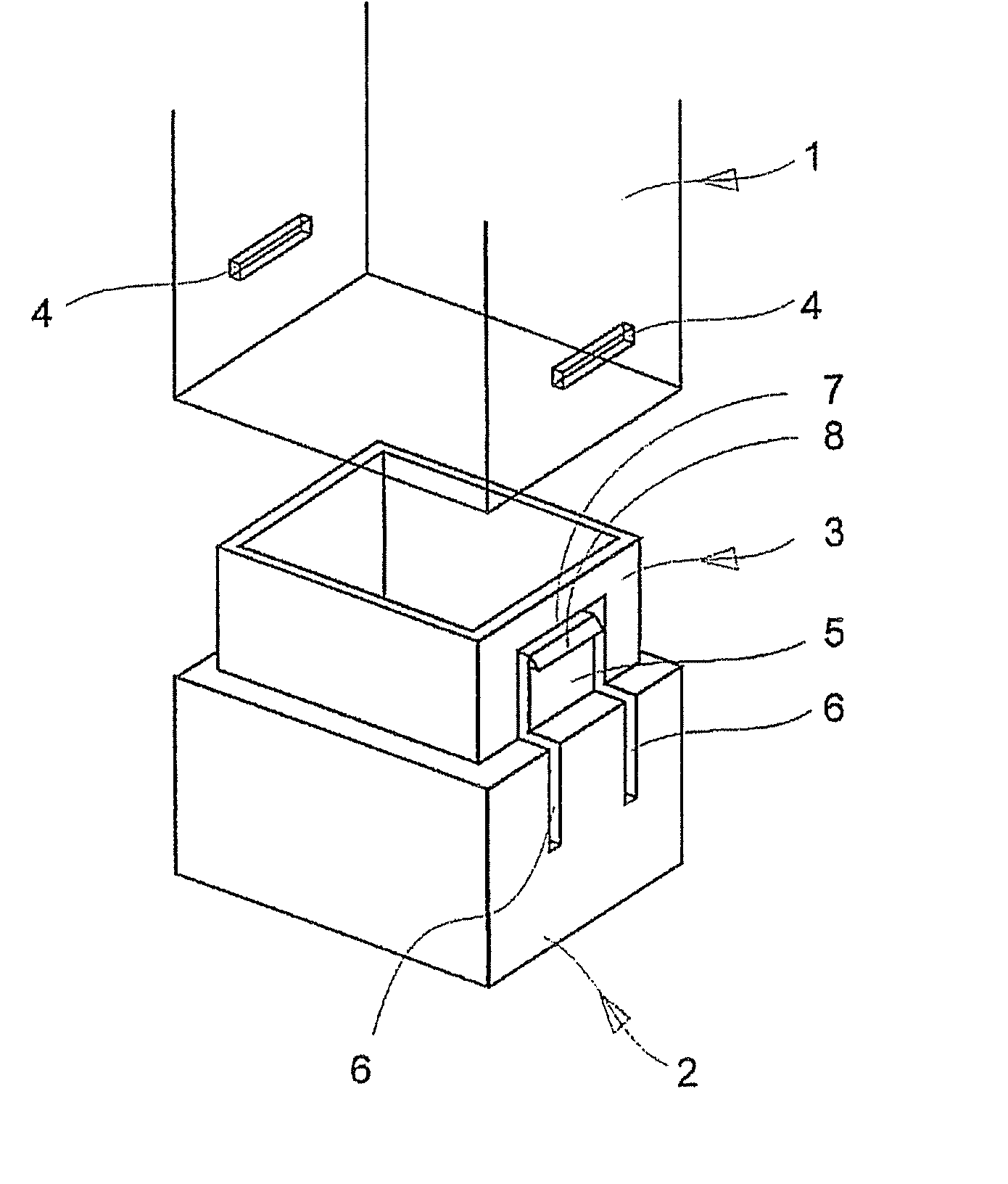
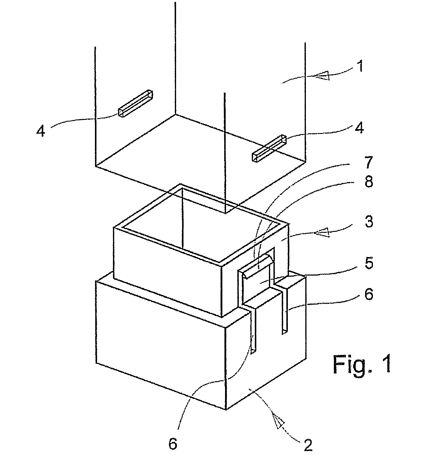
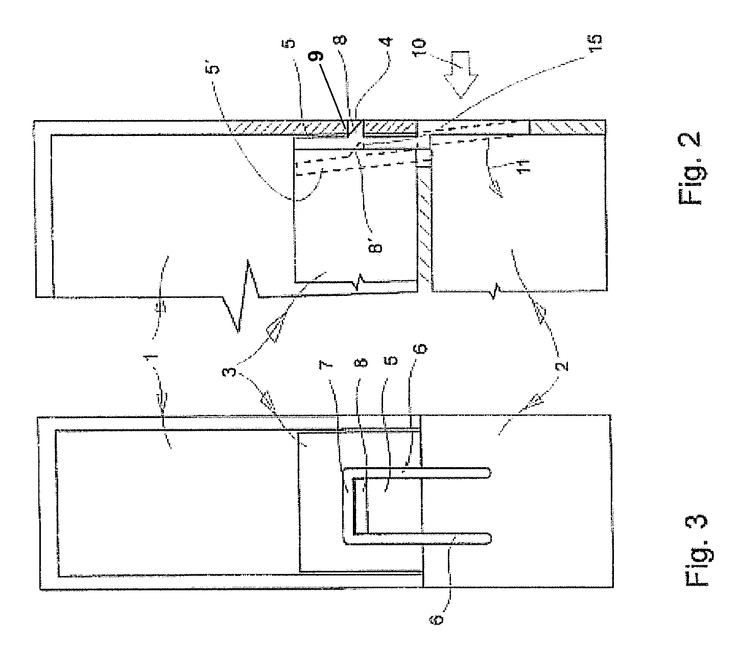
[0014] The container according to FIGS. 1 through 3 comprises an upper part 1 and a lower part 2 that snaps into the upper part 1. The two parts 1, 2 may be constructed of any desired material composition, such as for example, metal, synthetic materials, composite materials, and other similar materials. The two parts 1, 2 may be constructed as transparent, partially transparent, or not transparent. The terms “upper part” and “lower part” are interchangeable. It is therefore not important in which part 1, 2 the snap-in closure with the snap-in device 5, described below, is constructed. In the example of an embodiment shown in FIG. 1, the snap-in closure is disposed in or constructed out of a wall of the lower part 2 of the container. It is also advantageous that the lower part 2 of the container comprises a lower part of greater dimensions changing into an upper socket-type part 3 having smaller dimensions and being open on top. The construction of the snap-in device in the area of t...


PUM

PropertyMeasurementUnit
Fractionaaaaaaaaaa
Forceaaaaaaaaaa
Dimensionaaaaaaaaaa

Abstract

The invention relates to a container comprising a snap-in closure disposed between an upper part and a lower part of the container, the snap-in closure having a relatively strong holding or locking force and able to be opened relatively easily. The snap-in closure comprises a snap-in tab constructed out of the wall of one part of the container and detached along three sides, with a snap-in key disposed at the upper free end of the said snap-in closure and able to engage in a coordinated snap-in slit at the opposite container part.

Description

CLAIM OF PRIORITY [0001] This invention claims the benefit of German Application No. 202005007586.8, filed on May 13, 2005. FIELD OF THE INVENTION [0002] The claimed invention is a container comprising a snap-in closure disposed between an upper and a lower part, and specifically a container wherein the snap-in closure has a relatively strong locking force and is able to be opened easily. BACKGROUND OF THE INVENTION [0003] Containers having snap-in closures are known to the art in various embodiments. For example, it is known in the art to dispose a snap-in closure between an upper part and a lower part of a container, where the snap-in closure is constructed as knob closure. Such a closure, although easy to open, has a very weak holding or locking force. In order to store relatively heavy objects in a container, however, it is necessary to provide a snap-in closure that has a strong holding force and that facilitates construction at relatively low manufacturing costs. SUMMARY OF TH...

Claims


Application Information

Patent Timeline
IPC IPC(8): B65D45/16B65D39/00B65D43/02
CPCB65D43/021B65D2543/00101B65D2543/00277B65D2543/00296B65D2543/00314B65D2543/00509B65D2543/00574B65D2543/00666B65D2543/00694B65D2543/0074B65D2543/00805B65D2543/00925Y10S206/806Y10T292/42Y10T292/0895Y10T292/083Y10T292/438
Inventor ROESLER, PETER
Owner ROESLER PETER
Why Eureka
Try Eureka