Communication system for a fire alarm or security system

a communication system and fire alarm technology, applied in the field of alarm systems, can solve problems such as inconsistent data maintained in one database, complex current fire alarm and security control system, and use of separate data

Inactive Publication Date: 2007-05-03
VES
View PDF28 Cites 22 Cited by
  • Summary
  • Abstract
  • Description
  • Claims
  • Application Information

AI Technical Summary

Problems solved by technology

It will be appreciated that current fire alarm and security control systems are complex.
The result is a substantial investment in both time and money to design the layout of the system, identify the components incorporated in it and their operational requirements, determine the cost to install the system and bring it “on-line”, and the on-going costs of day-to-day operation, maintenance, and support.
Moreover, most manufacturers and installers are only concerned with initial sale of their product or service and do not focus on potential recurring revenues from the products and services they provide; i.e., those occurring after the system is up and operating.
As one example, a drawback with current systems is the use of separate databases one of which is maintained at the installation site of the system, and another of which is maintained at a monitoring site that is usually remote from the premises where the system is installed.
Unfortunately, it is often found that the data maintained in the one database is inconsistent with that maintained in the other.
Another problem occurring during the initial stage of system design is the significant number of changes which usually take place.
One is the cost of components.
As sensors, control panels, ancillary equipment is added or changed, so do component costs.
Specialized sensors for particular monitoring functions will especially add to the cost.
If changes are continually being made, and these are not timely provided to the contractor, his proposal will not be realistic causing him to lose the bid; or if it is awarded to him, subsequent disputes when he starts to go over budget or finds that he cannot complete the job within his bid.
In either instance, problems will result that are unnecessary.

Method used


Image

  • Communication system for a fire alarm or security system
  • Communication system for a fire alarm or security system
  • Communication system for a fire alarm or security system

Examples


Embodiment Construction

[0027] The following detailed description illustrates the invention by way of example and not by way of limitation. This description will clearly enable one skilled in the art to make and use the invention, and describes several embodiments, adaptations, variations, alternatives and uses of the invention, including what I presently believe is the best mode of carrying out the invention. As various changes could be made in the above constructions without departing from the scope of the invention, it is intended that all matter contained in the above description or shown in the accompanying drawings shall be interpreted as illustrative and not in a limiting sense.

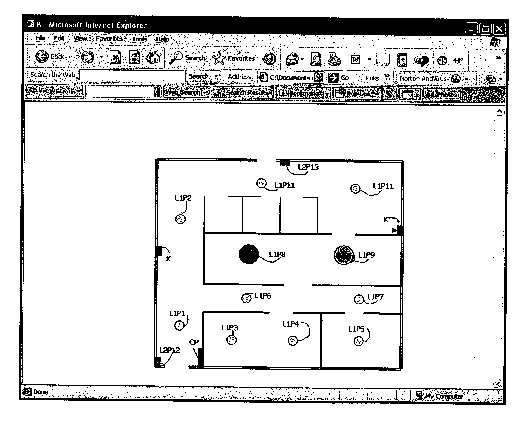
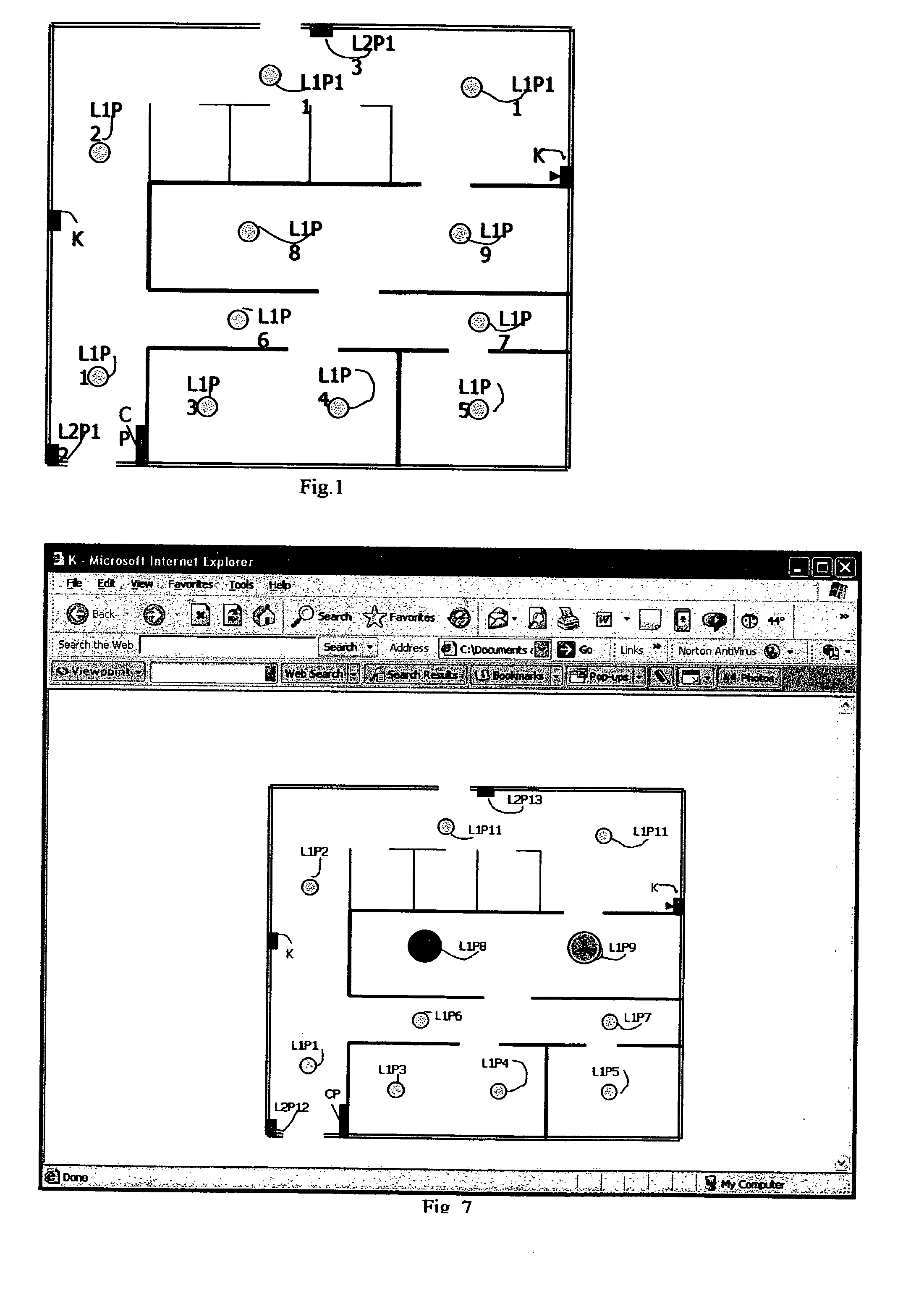
[0028] In accordance with the method of the invention, a fire alarm or security system indicated generally 10 is installed in a building, or the floor of a building, as shown in FIG. 1. System 10 includes a series of sensors or alarm devices indicated generally LlP1-L2P15. There are typically analog devices, but digital devi...


PUM


Abstract

A communications system for an alarm or security system. A plurality of sensors are installed in a facility detect an alarm condition together with a control unit interconnected with the sensors and to which an alarm indication is sent by a sensor going into alarm. A communications path is established by which an alarm signal is transmitted from the control unit to an alarm processing station. A central database, remote from the facility, is accessible from the alarm processing station and includes up-to-date, pertinent information relating to the facility including its address and description, information about the sensor that triggered the alarm, a past history of other alarms, and special instructions regarding how responders should respond in the event hazardous materials are located in an area of the facility where the sensor is located. The system further includes a communications capability for providing this information to responders in route to the facility, including text and graphic information.

Description

CROSS REFERENCE TO RELATED APPLICATIONS [0001] None STATEMENT REGARDING FEDERALLY SPONSORED RESEARCH OR DEVELOPMENT [0002] N / A BACKGROUND OF THE INVENTION [0003] This invention relates to the alarm systems including fire alarm and security systems in facilities such as office buildings, factories, and warehouses, and more particularly to a communications system by which an alarm situation occurring at the facility is reported to system managers, responders to emergency situations, and others, together with appropriate information stored in a central database relating to the facility, previous alarms occurring at the facility and other relevant information. [0004] There are several steps or stages involved in the design and installation of fire alarm and security systems. These typically include: [0005] system design including the preparation of installation drawings and bills of material; [0006] system bidding process; [0007] installation of various types of sensors, control panel(s...

Claims


Application Information

Patent Timeline
Patent Type & Authority Applications(United States)
IPC IPC(8): G08B1/08G08B1/00G08B25/00
CPCG08B25/009G08B25/14
Inventor SEELEY, JOHN E.BLACK, MITCHELL
Owner VES
Why Eureka
Try Eureka