Optical connector

a technology of optical connectors and connectors, applied in the field of optical connectors, can solve the problems of reducing the thickness of the latch, reducing the engagement force, and affecting the operation of the connector, so as to prevent accidental disconnection

Active Publication Date: 2007-05-03
FURUKAWA ELECTRIC CO LTD +3
View PDF2 Cites 117 Cited by
  • Summary
  • Abstract
  • Description
  • Claims
  • Application Information

AI Technical Summary

Benefits of technology

[0009] The present invention provides an optical connector with latch structure which minimizes the thickness of the latch and clearances in each part and implements a smooth connecting and disconnecting operations in order to decrease the size and weight, for the modular jack type optical connector that enables easier connecting and disconnecting.

Problems solved by technology

One of disadvantageous factor of using an optical connector is the size of its structure.
On the other hand, reducing the thickness of the latch has some cause for concerns.
In particular, it might cause decrease of engagement force.
Otherwise, when releasing the latch, an engaging projection formed on the latch might not be detached from the adapter because of excessive bending of the latch arm.

Method used


Image

  • Optical connector
  • Optical connector
  • Optical connector

Examples


first embodiment

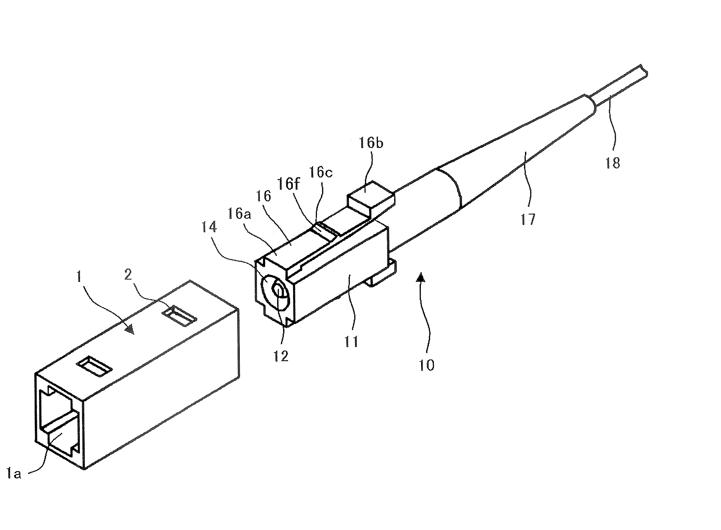
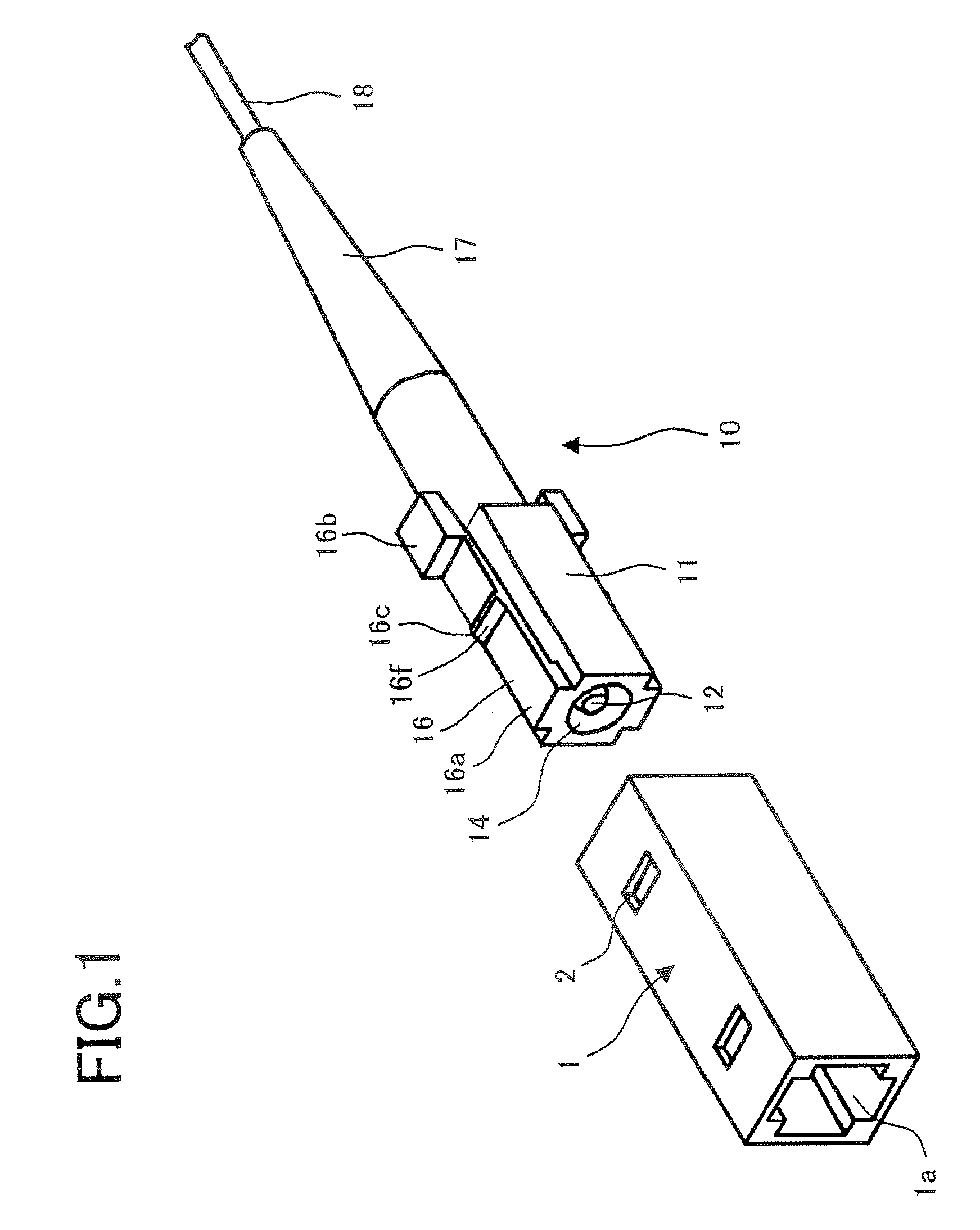
[0025]FIG. 1 is an external view of an optical connector, which is comprised of an optical connector plug 10 and an adapter 1 for connecting a pair of optical connector plugs in an embodiment of the present invention.

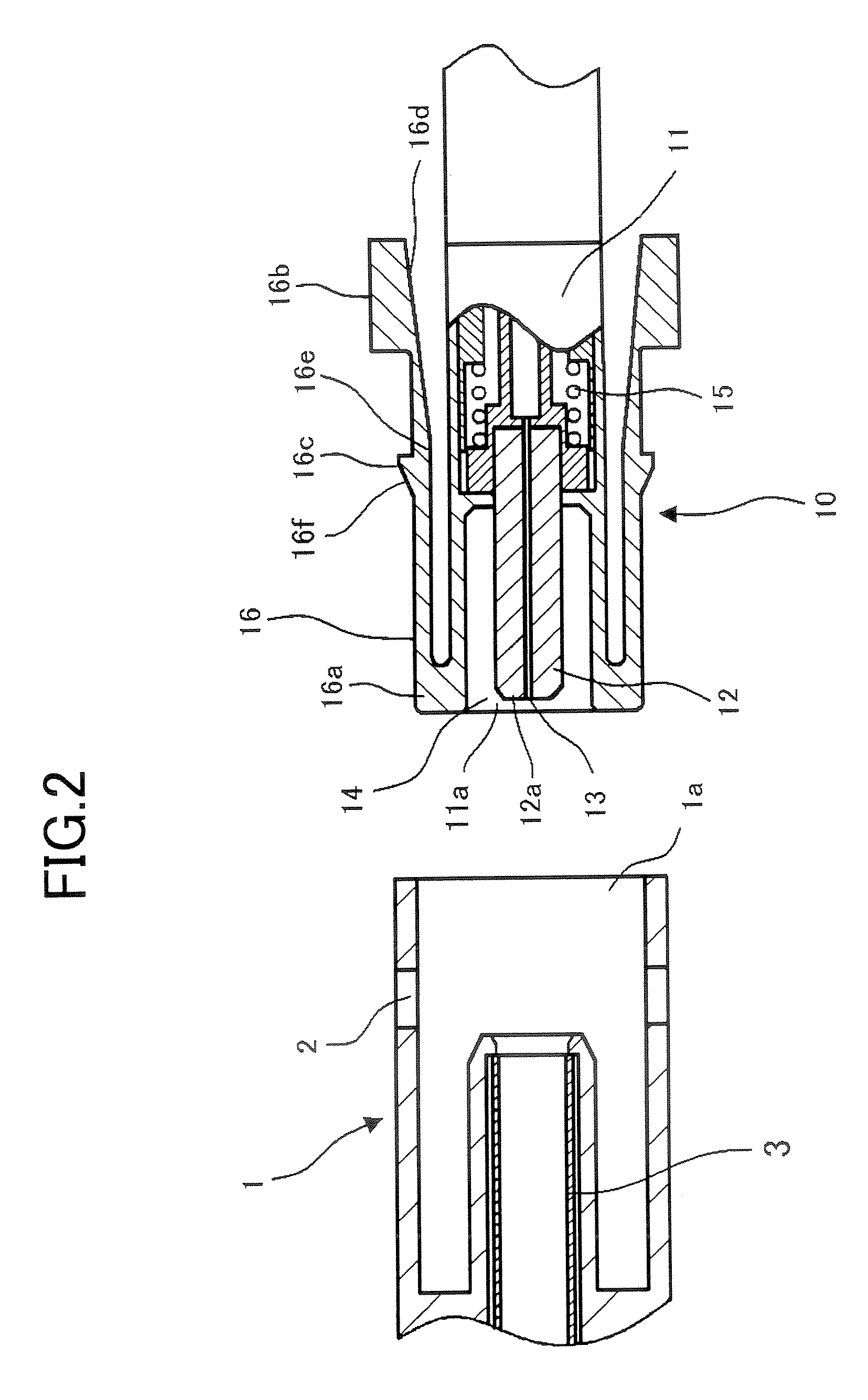
[0026]FIG. 2 shows a cross section of an engaging portion between the adapter 1 and the optical connector plug 10 shown in FIG. 1 described above. In FIG. 2, an optical fiber 13 to be connected is installed and held within a ferrule 12 such that its terminal end surface is exposed from a ferrule end face 12a, and the ferrule 12 is accommodated in a plug housing 11. In the ferrule 12 shown in FIG. 2, an optical fiber with single core is installed, but a plurality of optical fibers may be installed in one ferrule 12. For the material of the ferrule 12, ceramics such as zirconia, thermal plasticity or thermoset plastics, glass, or the like is often applied, or combinations of these materials may be used. Also, the optical fiber 13 is fixed with an adhesive agent or the li...

second embodiment

[0048] In FIG. 6 and FIG. 7, an optical connector includes an optical connector plug and a receptacle 21 with a ferrule 25 accommodated therein, capable to be connected to the optical connector plug.

[0049] The shape of the optical connector plug 30 including a latch 36 structure is the same as that of the first embodiment.

[0050] The receptacle 21, similar to the adapter in the first embodiment, has an engaging hole 22 capable to be connected with an engaging projection 36c that is provided in the latch 36 of the optical connector plug 30.

[0051] In FIG. 6, the optical connector plug 30 and the receptacle 21 respectively accommodate therein ferrules 33, 26 which hold a single core optical fiber. Also, a split sleeve 23 is installed in the receptacle 21 for highly accurately aligning respective ferrules to be connected.

[0052] Springs for pressing the ferrules may be provided in both of the optical connector plug and the receptacle, however the spring may be provided in one of the o...


PUM


Abstract

A cantilever type latch having the fixed end on the side of exposing the terminal end surface of the optical fiber is provided on the side of the plug housing. Near the center of the upper surface of the latch, an engaging projection which is to be engaged in the engaging hole formed in the adapter or the receptacle is formed. The engaging projection has the slope which decreases the height toward the fixed end side of the latch, in which the gradient of the slope is nearly equal to or greater than the rotation angle required for the elastic deformation of the latch with the fixed end functioned as the fulcrum. Thereby easy disconnecting of the latch is implemented.

Description

BACKGROUND OF THE INVENTION [0001] 1. Field of the Invention [0002] The invention relates to an optical connector which optically connects an optical fiber. [0003] 2. Description of the Related Art [0004] In general, there are optical connectors having a joint system which is a combination of a slider and a latch such as SC connector (JIS C 5973) and MPO connector (JIS C 5982), and the one having modular jack method as disclosed in Japanese Published Unexamined Patent Application No. 2000-147323. Both systems of optical connector are mainly used for connecting points of an optical fiber which needs to undergo frequent connecting and disconnecting in equipments or between equipments at indoor. [0005] On the other hand, for connection at outdoor, the mechanical splice or fusion splice is mainly used, but optical connectors described above are rarely used. [0006] As the rapid spread of Internet usage in homes in recent years, urgency of an optical connector that allows easier connectin...

Claims


Application Information

Patent Timeline
Patent Type & Authority Applications(United States)
IPC IPC(8): G02B6/36
CPCG02B6/3821G02B6/3825G02B6/3865G02B6/3893G02B6/36G02B6/38
Inventor SHIMOJI, NAOKOSHIINO, MASATOTOYONAGA, MASANOBUTERAKAWA, KUNIAKITANASE, HIROYUKINAKAJIMA, TATSUYAAWAMORI, MASASHITAKIZAWA, KAZUHIROSAITOH, DAIGOOHTSUKA, KENICHIRONISHIOKA, DAIZOHAMADA, MASAHIRO
Owner FURUKAWA ELECTRIC CO LTD
Why Eureka
Try Eureka