
Support for locating instrument guides

a technology of instrument guides and positioning guides, applied in the field of surgical instruments, can solve the problems of devices being limited to predetermined angular settings, and achieve the effect of efficiently and accurately setting the position, alignment and orientation of cutting blocks and other surgical instruments

Inactive Publication Date: 2007-05-03
DEPUY PROD INC
View PDF18 Cites 108 Cited by
  • Summary
  • Abstract
  • Description
  • Claims
  • Application Information

AI Technical Summary

Benefits of technology

[0009] The present invention provides a surgical instrument system that can be used to efficiently and accurately set the position, alignment and orientation of cutting blocks and other surgical instruments.
[0010] In one aspect, the present invention meets these objectives by providing a surgical instrument system for resecting a bone during joint arthroplasty. The system comprises a cutting instrument, an anchoring structure, a guide structure and an articulating linkage. The guide structure guides the path of the cutting instrument. The articulating linkage connects the anchoring structure to the guide structure, and includes a plurality of lockable ball joints arranged in series. Each ball joint provides for freedom of movement about three axes of rotation.

Problems solved by technology

U.S. Pat. No. 5,451,228 also utilizes an ankle clamp but allows for angular orientation in the anterior-posterior plane to predetermined angular orientations using a thumb actuated slide mechanism; the device is however limited to predetermined angular settings.

Method used


Image

  • Support for locating instrument guides
  • Support for locating instrument guides
  • Support for locating instrument guides

Examples


Embodiment Construction

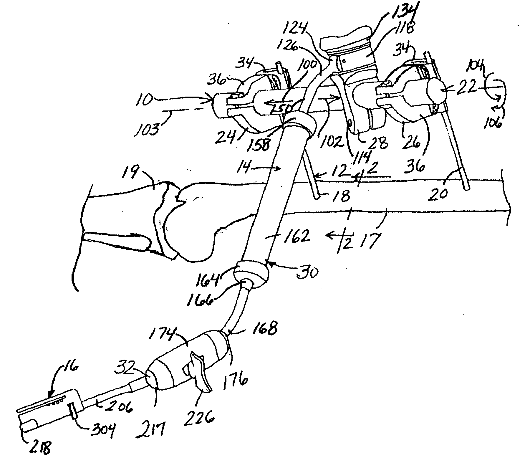
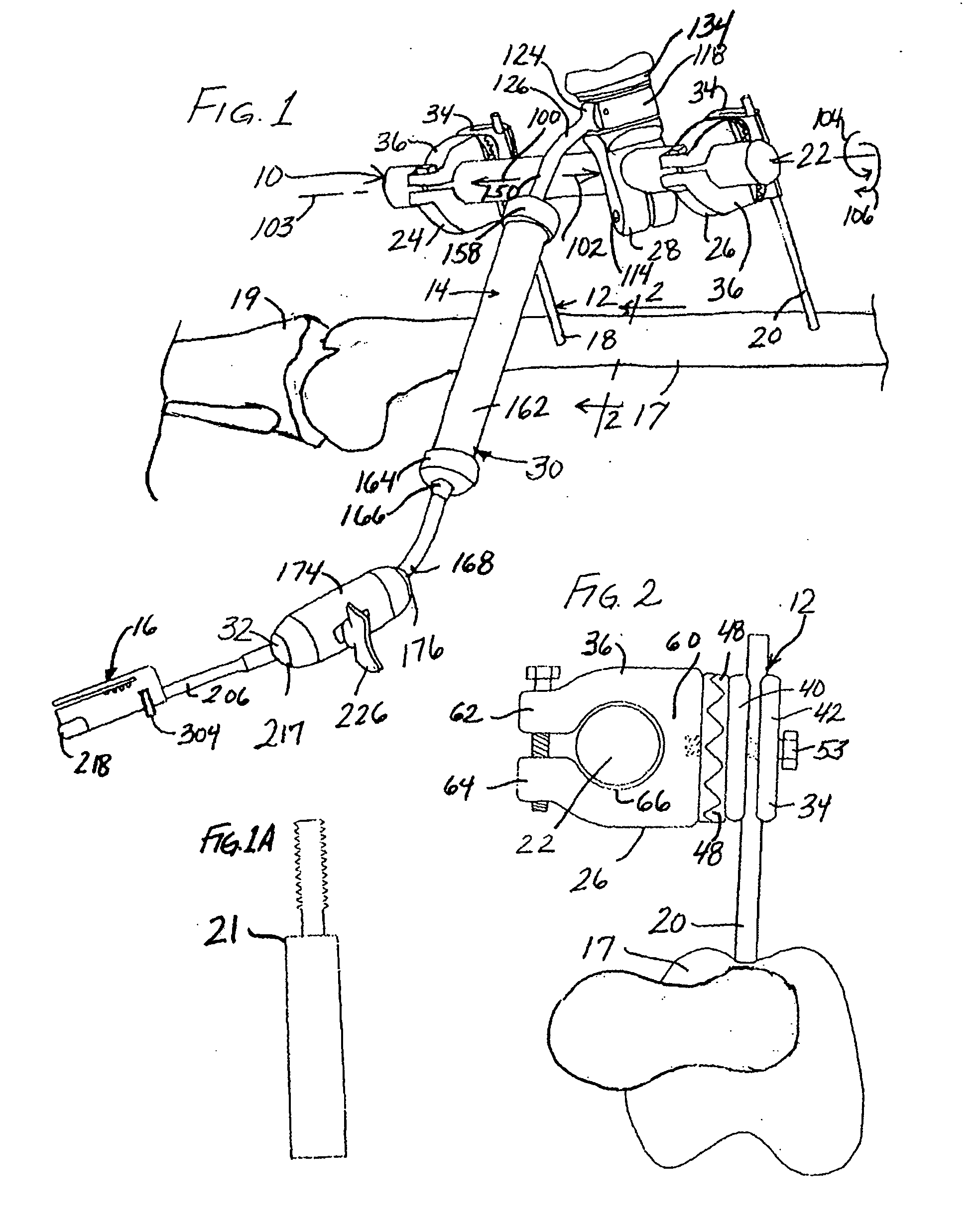
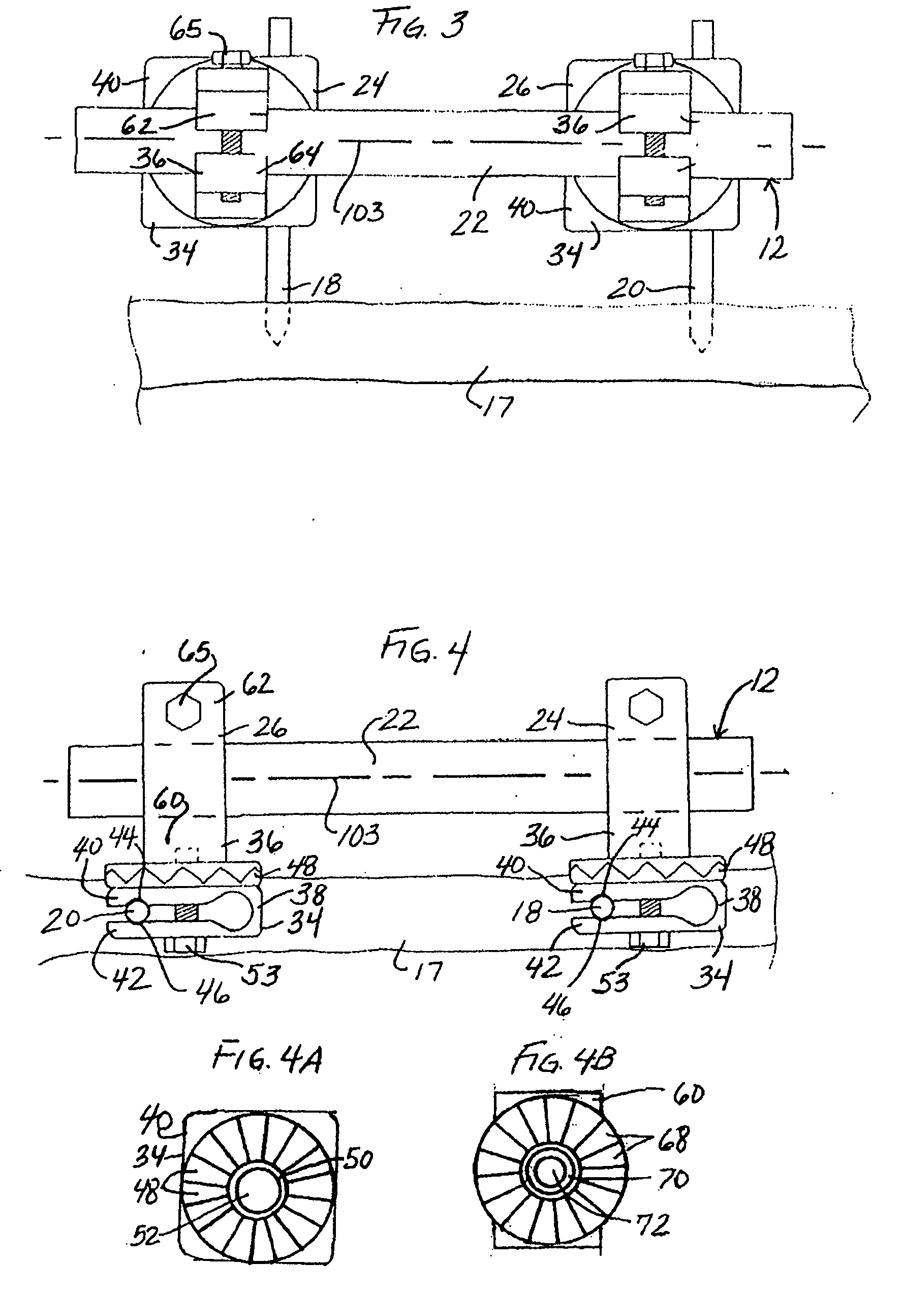
[0057] A first embodiment of an instrument system illustrating the principles of the present invention is illustrated at 10 in FIGS. 1-22. The first illustrated instrument system 10 comprises three main parts: an anchoring structure 12 that is mounted to a reference such as a bone shown at 17 in FIG. 1; an articulating linkage 14 that is connected to the anchoring structure 12; and a guide structure 16 that is connected to the articulating linkage. With this instrument set, the surgeon can rigidly fix the anchoring structure 12 to one of the patient's bones, move the guide structure 16 into a desired position and then lock the articulating linkage 14 to hold the guide structure 16 in the desired position. The guide structure 16 may then be fixed to the bone 17 or to a neighboring bone such as tibia 19 with fixation pins or the like if desired. The guide structure 16 may then be used to guide the path of a surgical instrument, such as a reciprocating saw shown at 21 in FIG. 1A, a mil...


PUM


Abstract

A surgical instrument system includes a cutting instrument, an anchoring structure, a guide structure and an articulating linkage. The anchoring structure can be fixed to a reference or benchmark, such as a location on the patient's bone. The articulating linkage connects the anchoring structure to the guide structure and includes a plurality of lockage ball joints arranged in series. Each ball joint provides for freedom of movement about three axes of rotation. The articulating linkage may include other structures allowing for additional rotational and translational degrees of freedom of movement for the guide structure with respect to the reference or benchmark. The system is useful in positioning, aligning and orienting a cutting block in joint arthroplasty, and may be useful in conjunction with computer assisted surgery. The system may also include computer navigation trackers for use in such computer assisted surgery.

Description

CROSS-REFERENCE TO RELATED APPLICATIONS [0001] Cross-reference is made to the following applications: DEP5597USNP titled, “METHOD OF RESECTING BONE” filed concurrently herewith which is incorporated herein by reference. BACKGROUND OF THE INVENTION [0002] The present invention relates to surgical instruments used to prepare a bone to receive a prosthetic implant, and more particularly, to such an instrument system used in conjunction with computer assisted surgery. [0003] When a skeletal joint is damaged, whether as a result of an accident or illness, a prosthetic replacement of the damaged joint may be necessary to relieve pain and to restore normal use to the joint. Typically the entire joint is replaced by means of a surgical procedure that involves removal of the ends of the corresponding damaged bones and replacement of these ends with prosthetic implants. This replacement of a native joint with a prosthetic joint is referred to as a primary total-joint arthroplasty. [0004] The ...

Claims


Application Information

Patent Timeline
Patent Type & Authority Applications(United States)
IPC IPC(8): A61F5/00
CPCA61B17/15A61B17/155A61B17/157A61B17/17A61B17/1764A61B19/26A61B19/5244A61B2019/5251A61B2019/5255A61B2017/1775A61B2034/2055A61B34/20A61B90/50A61B2034/2051A61B17/1775
Inventor WYSS, JOSEPH G.HOLM, MARA C.
Owner DEPUY PROD INC
Learn More