

Paper sheet take-out apparatus
a paper take-out and paper sheet technology, applied in the direction of transportation and packaging, thin material processing, article separation, etc., can solve the problems of unstable rate of paper sheet taking out, the periphery of the take-out roller does not sufficiently contact the surface of paper sheet, etc., to achieve sufficient frictional force and stably take out paper sheet
- Summary
- Abstract
- Description
- Claims
- Application Information
AI Technical Summary
Benefits of technology
Problems solved by technology
Method used
Image

Examples
first embodiment
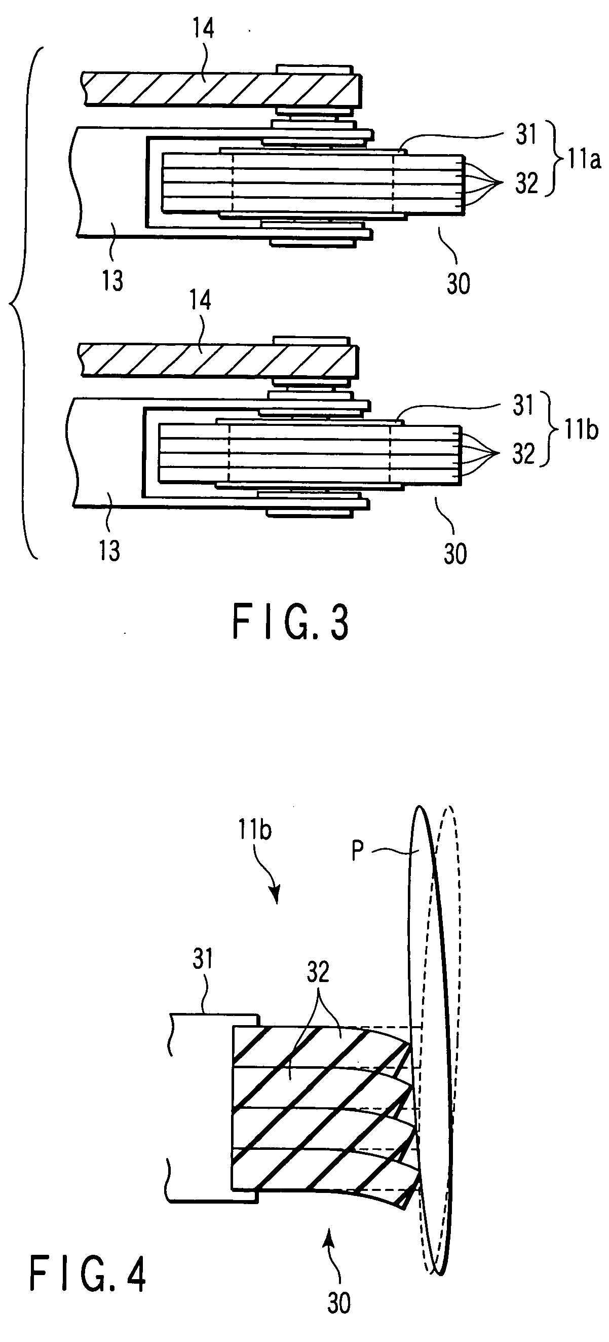
[0043] The upper take-out roller 11b according to the invention (hereinafter simply called a take-out roller 11b) is constructed by bonding a substantially cylindrical roller part 30 formed by closely stacking a plurality of circular rubber ring 32 in the axial direction, to the periphery of a substantially cylindrical core member 31 fixed to a rotation axle. In this embodiment, the roller part 30 having a width of 15 mm in the axial direction is constructed by closely stacking four equally-sized rubber rings 32, 3.75 mm in thickness in the axial direction, 60 mm in outer diameter, and 7 mm in thickness in the radial direction, in the axial direction. In this embodiment, each rubber ring 32 is made of the same rubber material, SUMITOMO RUBBER EM601 (EPDM) with a hardness of A60 / S.
[0044] The thickness of the rubber ring 32 in the axial direction is designed to be 3.75 mm in this embodiment, as described above, but is desirably 2 mm-4 mm. If the thickness of the rubber ring 32 is set ...
second embodiment
[0056] Next, an explanation will be given on a take-out roller 40 according to the invention with reference to FIG. 6. The take-out roller 40 is incorporated into the take-out apparatus 1, instead of the take-out rollers 11a, 11b, 12a and 12b described hereinbefore. The take-out roller 40 has the same structure and substantially the same function as the take-out rollers 11a, 11b, 12a and 12b, except for the structure of the roller part. Therefore, the components having the same functions are given the same reference numerals, and a detailed explanation will be omitted.
[0057] As shown in FIG. 6, the take-out roller 40 is provided with a roller part 41 formed by stacking rubber rings 42 and 44 around the outer periphery of the core member 31. One rubber ring 42 is made of relatively hard rubber, functions as a second rubber ring of the invention, and is 3 mm in the thickness in the axial direction. Except for the thickness in the axial direction, the ring 42 is made of the rubber mate...
third embodiment
[0065] Next, an explanation will be given on a take-out roller 50 according to the invention with reference to FIG. 8. The take-out roller 50 has the same structure and substantially the same function as the take-out rollers 11a, 11b, 12a and 12b, except for the structure of the roller part. Therefore, the components having the same functions are given the same reference numerals, and a detailed explanation will be omitted.
[0066] As shown in FIG. 8, the take-out roller 50 is provided with a substantially cylindrical roller part 51 wound on the periphery of the core member 31. The roller part 51 is formed cylindrical, made of the same rubber material as the take-out roller 11b of the first embodiment, and sized to 15 mm in thickness in the axial direction, 7 mm in thickness in the radial direction, and 60 mm in outside diameter. The roller part 51 has four circular slits 52 (cuts) dividing the periphery with equal intervals (3 mm). The depth of each slit in the radial direction is se...
PUM
| Property | Measurement | Unit |
|---|---|---|
| outer diameter | aaaaa | aaaaa |
| outer diameter | aaaaa | aaaaa |
| outer diameter | aaaaa | aaaaa |
Abstract
Description
Claims
Application Information