Driving apparatus

Inactive Publication Date: 2005-09-29
KONICA MINOLTA OPTO
View PDF6 Cites 3 Cited by
  • Summary
  • Abstract
  • Description
  • Claims
  • Application Information

AI Technical Summary

Benefits of technology

[0008] The present invention has been made in view of the above circumstances and has an object to overcome the above problems and to provide a driving apparatus with good

Problems solved by technology

In a compact camera used in for example a cellular phone, however, the movable body such as an optical lens is small in size.
This makes it difficult to secure the leaf spring by the screws as described in EP '589.
As the spring is reduced in size, a spring constant becomes larger, so that such small springs would be more susceptible to errors caused at the time of manufacture.
Further,

Method used


Image

  • Driving apparatus
  • Driving apparatus
  • Driving apparatus

Examples


Embodiment Construction

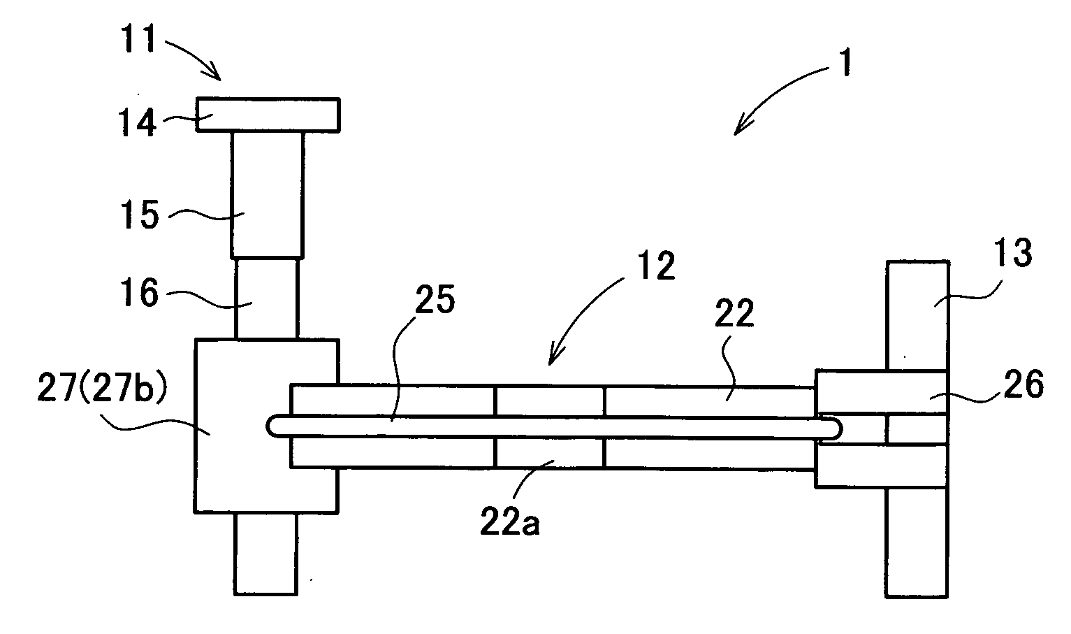
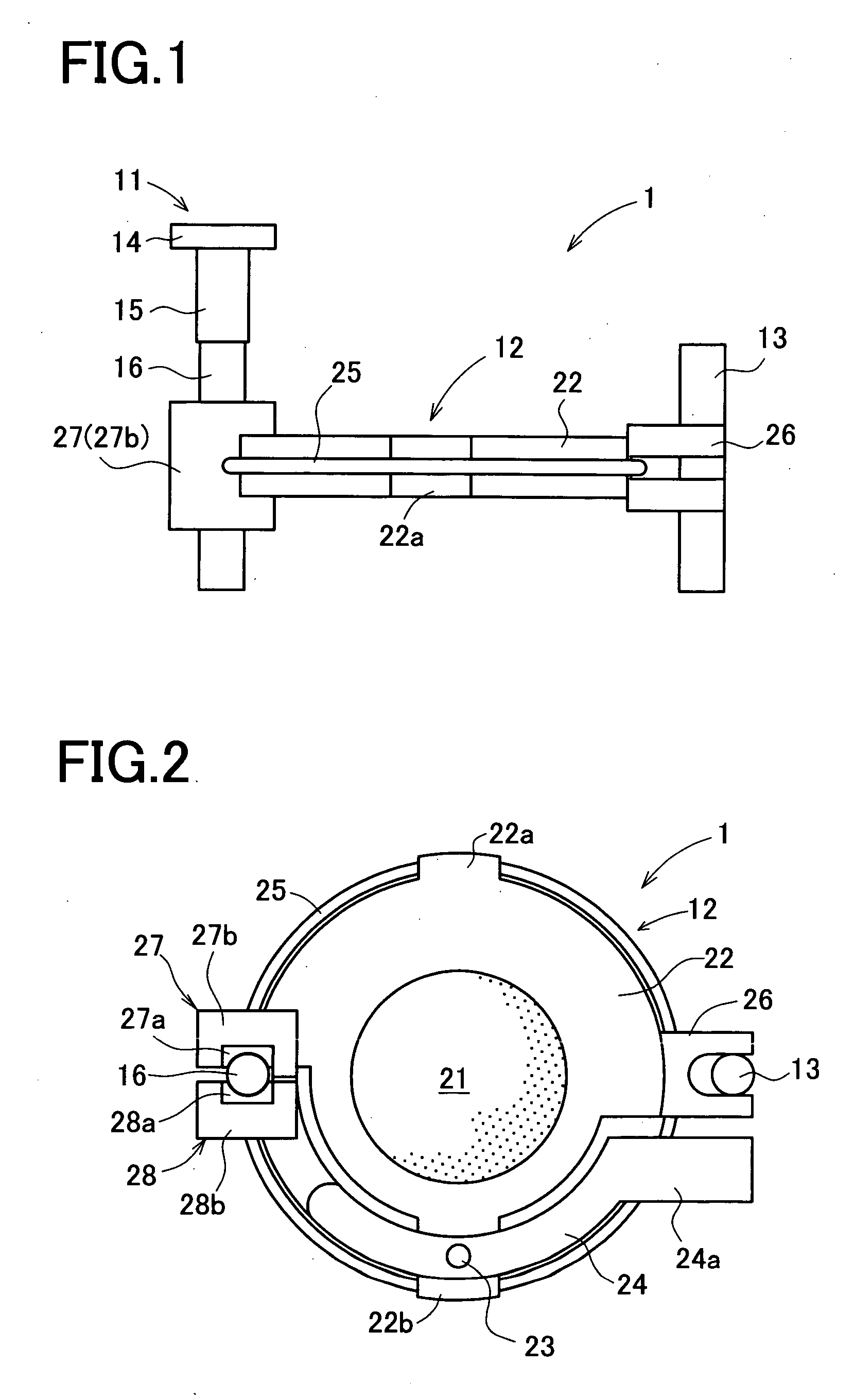
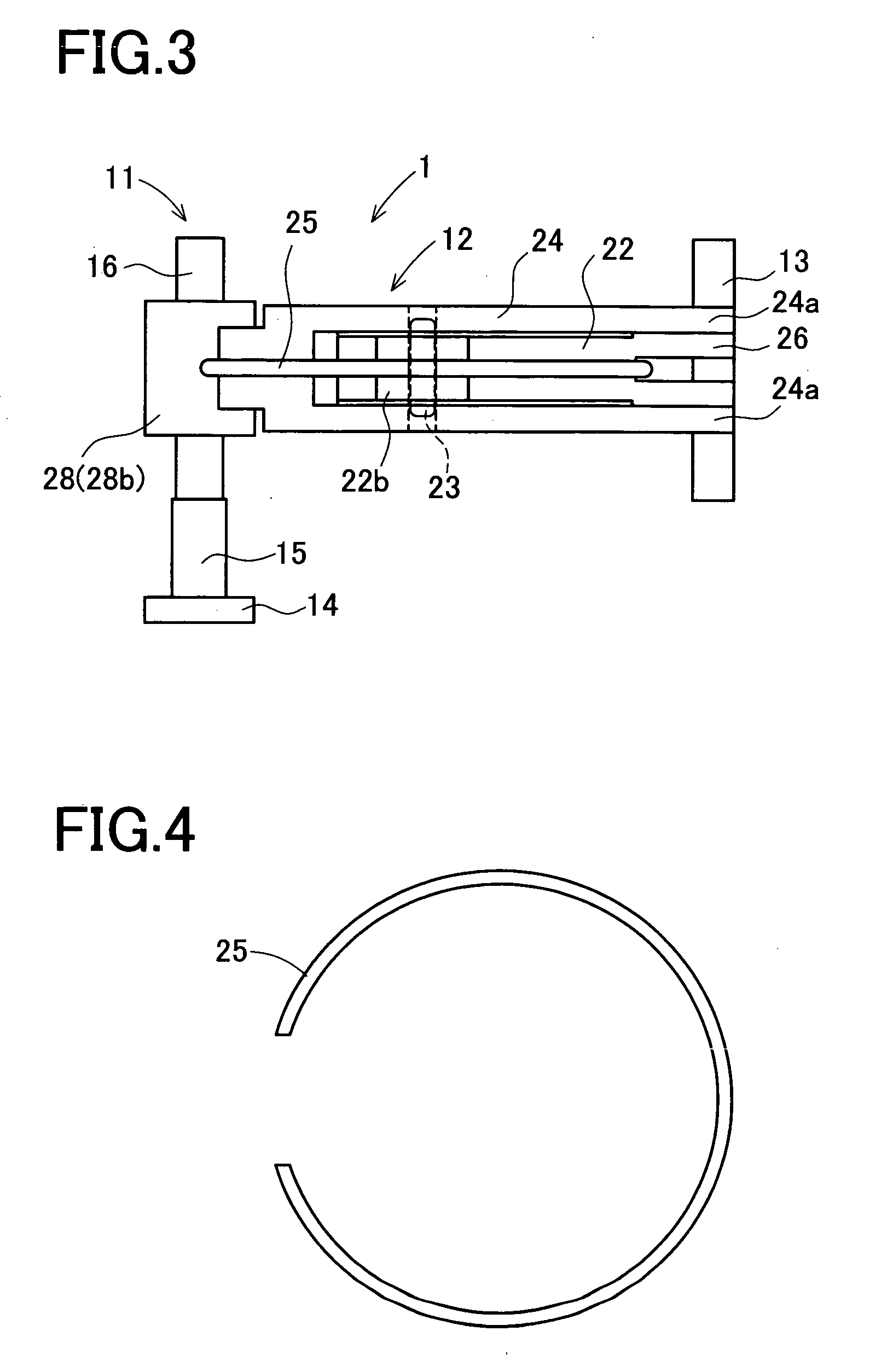
[0024] A detailed description of a preferred embodiment of the present invention will now be given referring to the accompanying drawings. In the present embodiment, the invention is applied to a driving apparatus arranged to move an optical lens mounted in a compact camera for a cellular phone and the like along an optical axis thereof by use of an electromechanical transducing actuator.

[0025] A driving apparatus 1 in the present embodiment includes an actuator 11, a movable unit 12 to be moved by the actuator 11, and a guide bar 13 for guiding the movable unit 12 in vertical movement as shown in FIGS. 1 and 2. FIG. 2 is a bottom view of the driving apparatus 1 seen from below in FIG. 1. The actuator 11 has a fixed member 14 to be fixed to a housing or another part of the camera, an electromechanical transducer 15, and a friction drive shaft 16, which are connected in order in an axial direction. The actuator 11 is arranged such that the movable unit 12 frictionally connected to t...


PUM


Abstract

A driving apparatus of the invention is arranged to drive an optical lens according to expansion and contraction of an electromechanical transducer. The driving apparatus comprises a fixed member connected to one end of the electromechanical transducer in a direction of expansion and contraction; a friction drive shaft connected to the other end of the electromechanical transducer; a hinge fixedly provided relative to the optical lens; a first frictional connecting part fixedly provided relative to the optical lens; a second frictional connecting part which is movably provided relative to the hinge and grasps the frictional drive shaft in cooperation with the first frictional connecting part from a direction perpendicular to the expansion and contraction direction of the electromechanical transducer; and a spring mounted extending around the optical lens and pinch the first and the second frictional connecting parts between both ends of the spring.

Description

CROSS-REFERENCE TO RELATED APPLICATIONS [0001] This application is based upon and claims the benefit of priority from the prior Japanese Patent Application No. 2004-96698 filed on Mar. 29, 2004, the entire contents of which are incorporated herein by reference. BACKGROUND OF THE INVENTION [0002] 1. Field of the Invention [0003] The present invention relates to a driving apparatus for moving an optical lens in a direction of an optical axis thereof. More particularly, the present invention relates to a driving apparatus constructed of an electromechanical transducing actuator using an electromechanical transducer such as a piezoelectric element, an electrostrictive element, and a magnetostrictive element. [0004] 2. Description of Related Art [0005] As a driving apparatus, there has been used an electromechanical transducing actuator for moving a movable unit by utilizing an electromechanical transducer such as a piezoelectric element, an electrostrictive element, or a magnetostrictiv...

Claims


Application Information

Patent Timeline
IPC IPC(8): G02B7/04G02B7/08H01L41/09H02N2/00
CPCH02N2/025G02B7/08
Inventor OKAMOTO, YASUHIRO
Owner KONICA MINOLTA OPTO
Why Eureka
Try Eureka