Hybrid pads for disc brakes

Inactive Publication Date: 2007-11-22
HIROMASA OKAMURA
View PDF5 Cites 3 Cited by
  • Summary
  • Abstract
  • Description
  • Claims
  • Application Information

AI Technical Summary

Benefits of technology

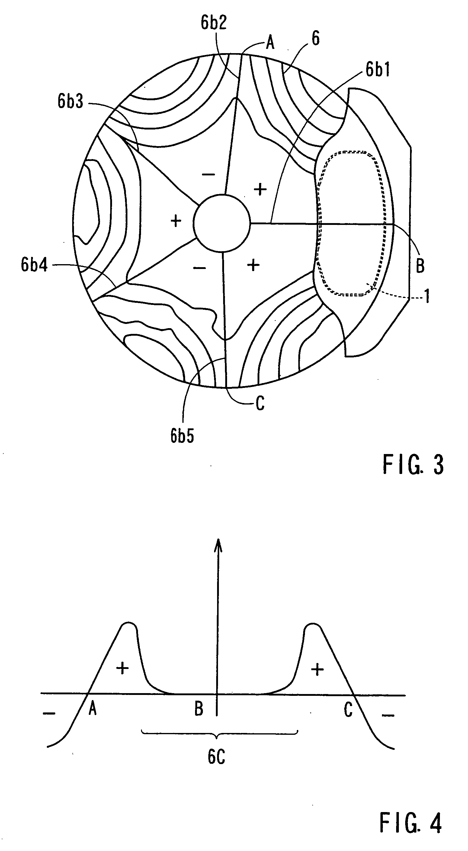
[0013]This configuration makes it possible to reduce a brake noise while maintaining a good brake feeling. In a mechanism capable of reducing the brake noise properly, vibrations in the thickness direction appear in the disc rotor at a braking time, and the vibrations have a plurality of fixed nodes. Moreover, at least one fixed node is positioned substantially at the center of the pad. In this pad, the second friction member of high hardness and high μ is positioned at that fixed node. According to this pad, therefore, it is possible to obtain the sufficient frictional force while suppressing the occurrence of the brake noise.
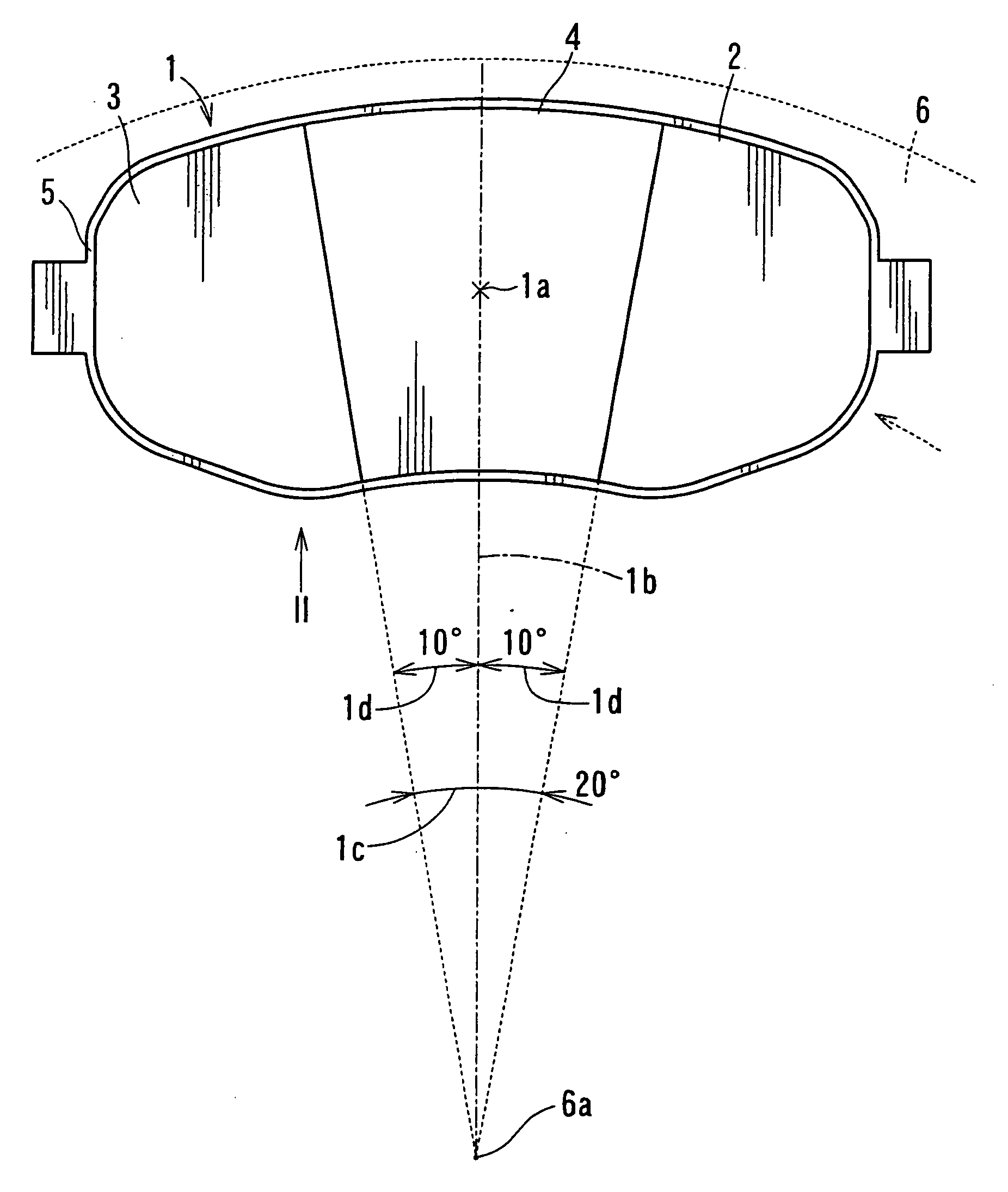
[0015]In another aspect of the present invention, the second friction member has a width, which can be positioned in an area within a center angle of 20° on the center of rotation of the disc rotor. Therefore, the second friction member of the high hardness and the high μ is positioned at the fixed node positioned generally at the center of the pad, and the width of the second friction member being positioned within the center angle of 20° contributes to holding the fixed node substantially in the center of the pad. According to this configuration, therefore, it is possible to obtain the sufficient frictional force while suppressing the occurrence of the brake noise.
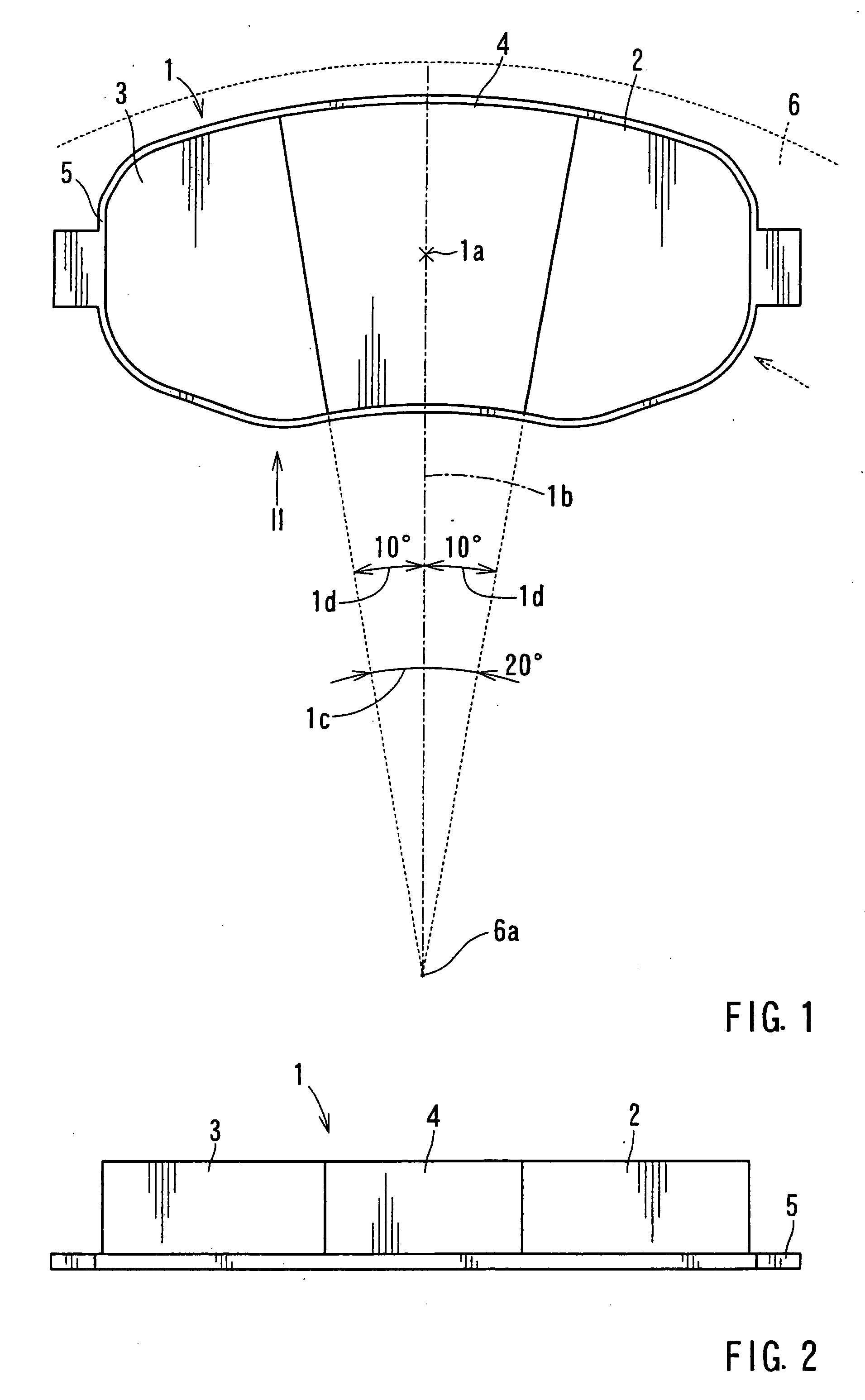
[0016]In another aspect of the present invention, the second friction member has a width length of 30 mm in the longitudinal direction of the pad. Therefore, the second friction member of the high hardness and the high μ is positioned at the fixed node positioned generally at the center of the pad, and the width of the second friction member is set within 30 mm so as to push only in the vicinity of the fixed node. Therefore, it is possible to obtain the sufficient frictional force while suppressing the occurrence of the brake noise.
[0017]In another aspect of the present invention, the Young's modulus E2 of the second friction member is set two times or more as high as the Young's modulus E1 of the first friction members, preferably 2 to 4 times. According to this construction, it is possible to reduce the brake noise and obtain a sufficient brake feeling.
[0018]In another aspect of the present invention, the first friction member includes a sliding area at the rotor rotation inlet portion and at the rotor rotation outlet portion of the pad. The individual sliding areas can be 40 to 60% of A1. Therefore, the first friction member of the rotor rotation inlet portion and the first friction member of the rotor rotation outlet portion can have substantially equal sliding areas. As a result, the central portion of the second friction member can be positioned substantially at the center of the pad. As a result, the second friction member can be reliably positioned with respect to the fixed node of the vibrations of the disc rotor, which occurs at the substantially center position of the pad. Thus, it is possible to suppress the brake noise reliably.
[0019]In another aspect of the present invention, chamfered portions cut out obliquely of the thickness direction of the friction members can be omitted. As a result, the individual friction members can maintain the same sliding areas to contact with the disc rotor 6, independently of the wear. After the friction members were worn, therefore, it is possible to obtain the same braking force and brake feeling as before any wear. Moreover, it is possible to reduce the brake noise similar to before any wear.

Problems solved by technology

In this case, it is not clear how the steps of the friction member change while the braking operations are being repeated, thereby leaving the effect of the stepped friction members indefinite.
As the wear advances, therefore, the heights of the individual friction members become different, thereby causing a problem of the brake feeling deteriorated.

Method used


Image

  • Hybrid pads for disc brakes
  • Hybrid pads for disc brakes
  • Hybrid pads for disc brakes

Examples


Embodiment Construction

[0026]Each of the additional features and teachings disclosed above and below may be utilized separately or in conjunction with other features and teachings to provide improved hybrid pads. Representative examples of the present invention, which examples utilize many of these additional features and teachings both separately and in conjunction with one another, will now be described in detail with reference to the attached drawings. This detailed description is merely intended to teach a person of skill in the art further details for practicing preferred aspects of the present teachings and is not intended to limit the scope of the invention. Only the claims define the scope of the claimed invention. Therefore, combinations of features and steps disclosed in the following detailed description may not be necessary to practice the invention in the broadest sense, and are instead taught merely to particularly describe representative examples of the invention. Moreover, various features...


PUM


Abstract

A hybrid pad for a disc brake has first friction members and a second friction member. The first friction members can be positioned at a rotor rotation inlet portion and at a rotor rotation outlet portion of the pad. The second friction member can be positioned at a central portion of the pad. The first friction members include a Young's modulus E1, a friction coefficient μ1 and a sum of the sliding areas A1 of the paired first friction members to come into sliding contact with the disc rotor. The second friction member has a Young's modulus E2, a friction coefficient μ2 and a sliding area A2 to come into sliding contact with the disc rotor. The μ2 is higher than the μ1, the E2 is higher than the E1, and (E2×A2) / (E1×A1) is 0.8 or more and 1.2 or less.

Description

[0001]This application claims priority to Japanese patent application serial number 2006-138988, 2006-328145, 2007-37681, the contents of which are incorporated herein by reference.BACKGROUND OF THE INVENTION[0002]The present invention relates to hybrid pads for disc brakes, which include a plurality of friction members having different characteristics.[0003]In the prior art, hybrid pads have been described in U.S. Pat. No. 4,926,978 ('978 Patent), JP-A-2004-125081 ('081 Patent), JP-A-2003-172385 ('385 Patent), JP-A-9-112606 ('606 Patent), and JP-A-2000-120738 ('738 Patent).[0004]The hybrid pad, as described in the '978 Patent, has friction members of different degrees of hardness. The pad has a hard friction member at a central portion and soft friction members at the two side portions. This construction aims at suppressing an uneven wear of a disc rotor for the pad to come into sliding contact with.[0005]The hybrid pad, as disclosed in 081 Patent, has a plurality of friction membe...

Claims


Application Information

Patent Timeline
IPC IPC(8): F16D69/00
CPCF16D2069/002F16D69/00
Inventor HIROMASA, OKAMURA
Owner HIROMASA OKAMURA
Why Eureka
Try Eureka