Plastic bottle closure, plastic bottle including the same, and plastic bottle closure opener

a technology of plastic bottle and opening, which is applied in the field of plastic bottle closure, can solve the problems of increasing the amount of resin required for forming the closure, the closure would not give sufficient frictional force to weak grip users, and the manufacturing cost is significant, so as to achieve the effect of increasing the amount of resin required, increasing the manufacturing cost, and sufficient frictional for

Inactive Publication Date: 2011-09-15
MUKUNOKI CHUICHIRO
View PDF4 Cites 24 Cited by
  • Summary
  • Abstract
  • Description
  • Claims
  • Application Information

AI Technical Summary

Benefits of technology

[0022]However, the first conventional technique has a problem that minor increase in the outer circumferential form of the closure would not give sufficient frictional force to weak grip users. In addition, to obtain sufficient friction, it is inevitable to significantly expand the outer form of the closure, and this significantly increases an amount of resin required for forming the closure, thus causing a problem of significant increase in manufacturing costs.

Problems solved by technology

However, the first conventional technique has a problem that minor increase in the outer circumferential form of the closure would not give sufficient frictional force to weak grip users.
In addition, to obtain sufficient friction, it is inevitable to significantly expand the outer form of the closure, and this significantly increases an amount of resin required for forming the closure, thus causing a problem of significant increase in manufacturing costs.
In addition, in the second conventional technique, when trying to form a sufficient protrusion or the like for fingers to catch, as in the first conventional technique described above, the amount of resin required for forming the closure increases accordingly, thus causing a problem of increase in the manufacturing costs.
In addition, the third conventional technique has a problem that simply forming an outer circumferential form of the closure into a polygonal shape will not prevent slippage of hands when opening the closure, and thus it is not possible to expect a significant effect for allowing weak grip users to open the closure.
In addition, the fourth conventional technique has a problem that one plastic bottle is not sufficient for opening the plastic bottle, and at least two plastic bottles of the same type are necessary for opening the closure.

Method used


Image

  • Plastic bottle closure, plastic bottle including the same, and plastic bottle closure opener
  • Plastic bottle closure, plastic bottle including the same, and plastic bottle closure opener
  • Plastic bottle closure, plastic bottle including the same, and plastic bottle closure opener

Examples


first embodiment

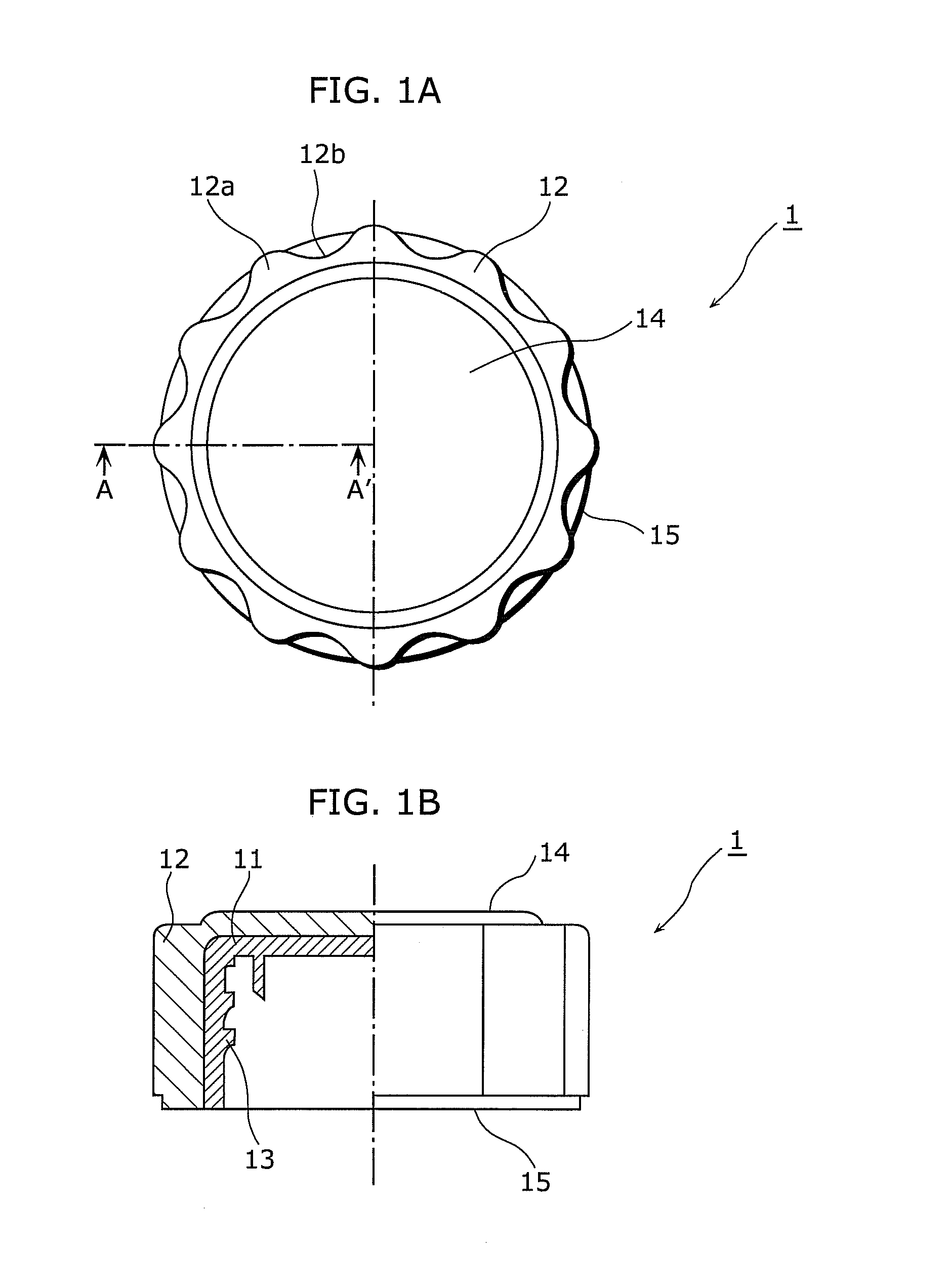
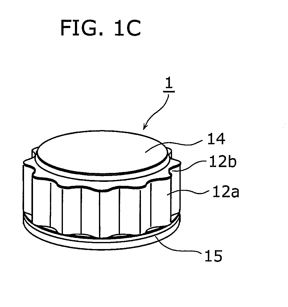
[0089]First, a closure 1 according to a first embodiment of the present invention will be described in detail with reference to the drawings. FIG. 1A is a plan view of the closure 1 according to the first embodiment of the present invention, and FIG. 1B is a partially cutaway cross-sectional side view of the closure shown in FIG. 1A. A cross-sectional portion in FIG. 1B shows a cross section of the closure when cut away along line A-A′ shown in FIG. 1A. In addition, FIG. 1C is an external perspective view of the closure shown in FIGS. 1A and 1B.

[0090]As shown in FIGS. 1A to 1C, the closure 1 according to the first embodiment of the present invention includes a closure base portion 11 and a concavo-convex portion 12.

[0091]The closure base portion 11 has a capped cylindrical shape, and, for example, is the same as an existing closure included in a plastic bottle available on the market. Accordingly, in an inner circumferential portion of the closure base portion 11, a screw portion 13...

second embodiment

[0124]Next, the following will describe a closure 2 according to a second embodiment of the present invention. FIG. 7A is a plan view of the closure 2 according to the second embodiment of the present invention, and FIG. 7B is a partially cutaway cross-sectional side view of the closure 2 shown in FIG. 7A. A cross-sectional portion in FIG. 7B shows a cross section of the closure when cut away along line B-B′ shown in FIG. 7A. FIG. 7C is an external perspective view of the closure shown in FIGS. 7A and 7B.

[0125]The closure 2 according to a second embodiment of the present invention is characterized in that the concavo-convex portion 22 formed using a dodecagonal socket wrench hole is formed only in a portion in a height direction of the closure.

[0126]The closure 2 according to the second embodiment of the present invention as shown in FIGS. 7A to 7C includes a concavo-convex portion only in an upper part of the lateral circumferential portion of the closure 2.

[0127]Note that the same...

third embodiment

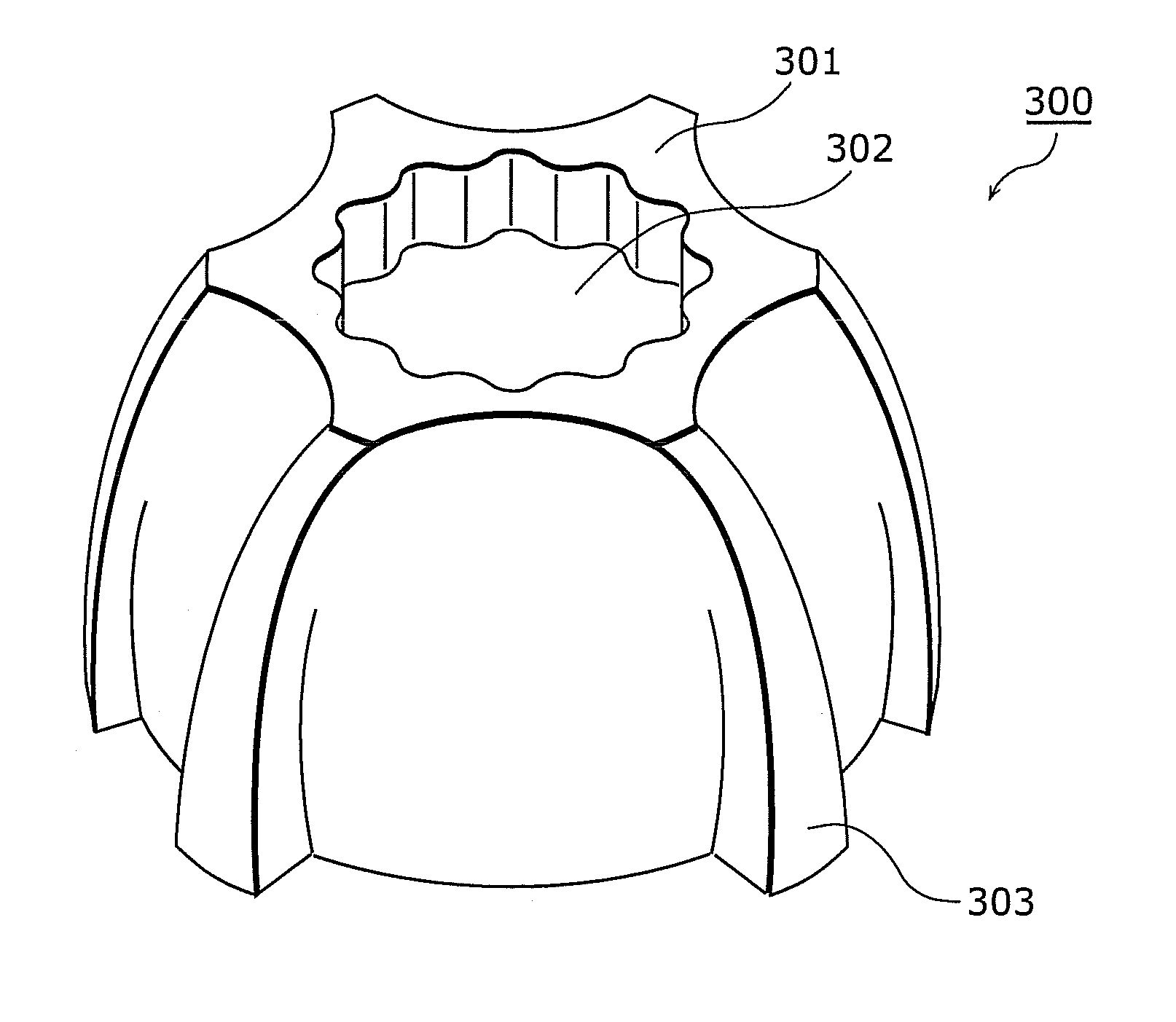
[0133]Next, the following will describe a closure 3 according to a third embodiment of the present invention. FIG. 8A is a plan view of the closure 3 according to the third embodiment of the present invention, and FIG. 8B is a partially cutaway cross-sectional side view of the closure 3 shown in FIG. 8A. A cross-sectional portion in FIG. 8B shows a cross section of the closure when cut away along line C-C′ shown in FIG. 8A. FIG. 8C is an external perspective view of the closure shown in FIGS. 8A and 8B.

[0134]The closure 3 according to the third embodiment as shown in FIGS. 8A to 8C includes a concavo-convex portion only in a lower part of the lateral circumferential portion of the closure 3.

[0135]Note that the same configurations in FIGS. 8A to 8C as those of the closure 1 according to the first embodiment of the present invention are assigned with the same numerical references, and the descriptions thereof will be omitted.

[0136]As shown in FIGS. 8A to 8C, the closure 3 according to...


PUM

PropertyMeasurementUnit
diameteraaaaaaaaaa
sizeaaaaaaaaaa
thicknessaaaaaaaaaa

Abstract

A plastic bottle closure, which is screwed onto an opening of a plastic bottle, has an outer form in which an outer circumferential portion fits in a hole of a standardized dodecagonal socket wrench. The outer circumferential portion of the plastic bottle closure includes a concavo-convex portion including a plurality of convex portions and a plurality of concave portions. The concavo-convex portion fits in a convexo-concave portion of the hole of the standardized dodecagonal socket wrench.

Description

CROSS REFERENCE TO RELATED APPLICATION[0001]This is a continuation application of PCT application No. PCT / JP2009 / 006268 filed on Nov. 20, 2009, designating the United States of America.BACKGROUND OF THE INVENTION[0002](1) Field of the Invention[0003]The present invention relates to a plastic bottle closure made of resin, a plastic bottle including the closure, and an opener for the plastic bottle closure.[0004](2) Description of the Related Art[0005]In recent years, plastic bottles are widely used for containing tea, mineral water, soft drink, and so on. A plastic bottle is composed of: a bottle body for containing drink such as tea, and a closure for sealing an opening of the bottle body.[0006]Screw grooves are formed in each of an outer circumferential portion of the opening and an inner circumferential portion of the closure, and the opening is sealed by screwing the closure onto the opening. In addition, a fixing ring is engaged in the opening, and in a state before the plastic ...

Claims


Application Information

Patent Timeline
Patent Type & Authority Applications(United States)
IPC IPC(8): B65D51/00B65D41/34B67B7/00
CPCB29C45/14B29C45/372B67B7/18B65D41/0485B29L2031/565
Inventor MUKUNOKI, CHUICHIRO
Owner MUKUNOKI CHUICHIRO
Why Eureka
Try Eureka