Radio frequency holographic transformer

a holographic transformer and radio frequency technology, applied in the direction of antennas, electrical equipment, etc., can solve the problems of rf lens antennas that typically have a narrow instantaneous bandwidth and are known to suffer from significant drawbacks, and achieve the effect of different frequency bandwidths, rapid and convenient programming

Active Publication Date: 2007-05-10
NORTHROP GRUMMAN SYST CORP
View PDF3 Cites 22 Cited by
  • Summary
  • Abstract
  • Description
  • Claims
  • Application Information

AI Technical Summary

Benefits of technology

[0009] It will be appreciated from the foregoing that the present invention represents a significant advance in RF lens type antennas. In particular, the invention provides an RF hologram that can be rapidly and conveniently programmed to perform a desired refraction effect on

Problems solved by technology

RF lens type antennas have long been recognized for their advantages of high gain and very good interference rejection, but are also known to suffer from significant drawbacks.
Specifically, RF lens antennas typically have a narrow instantaneous bandwidth, are limited to a handling single beam, and have a direction and frequency that are fixed by the specific hardware

Method used


Image

  • Radio frequency holographic transformer
  • Radio frequency holographic transformer
  • Radio frequency holographic transformer

Examples


Embodiment Construction

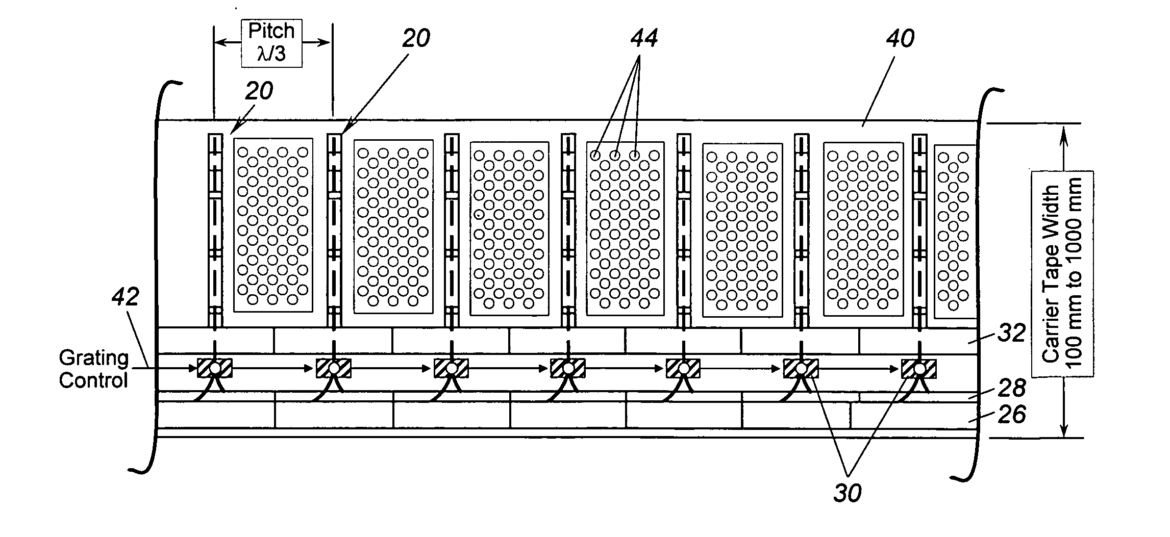
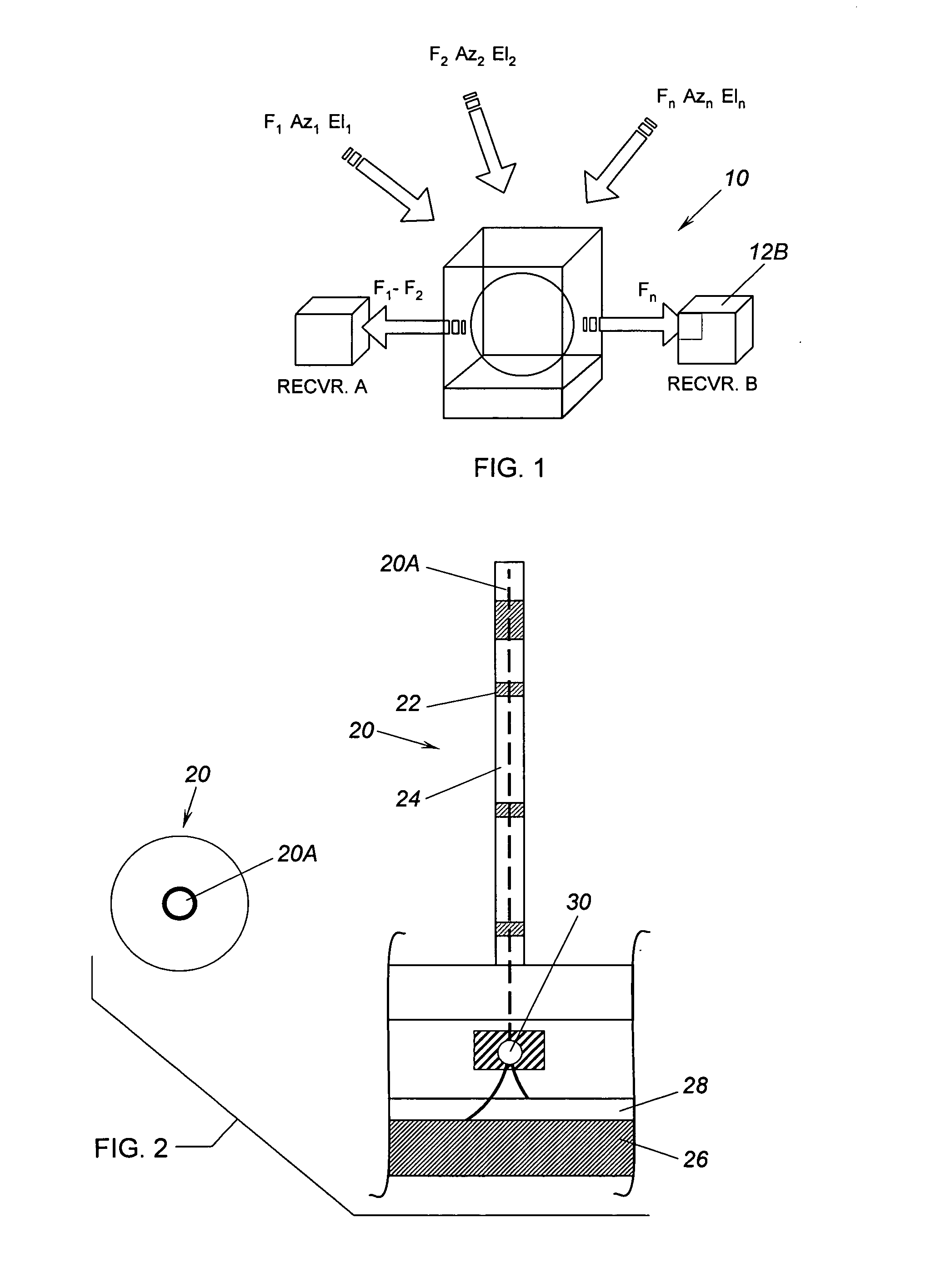
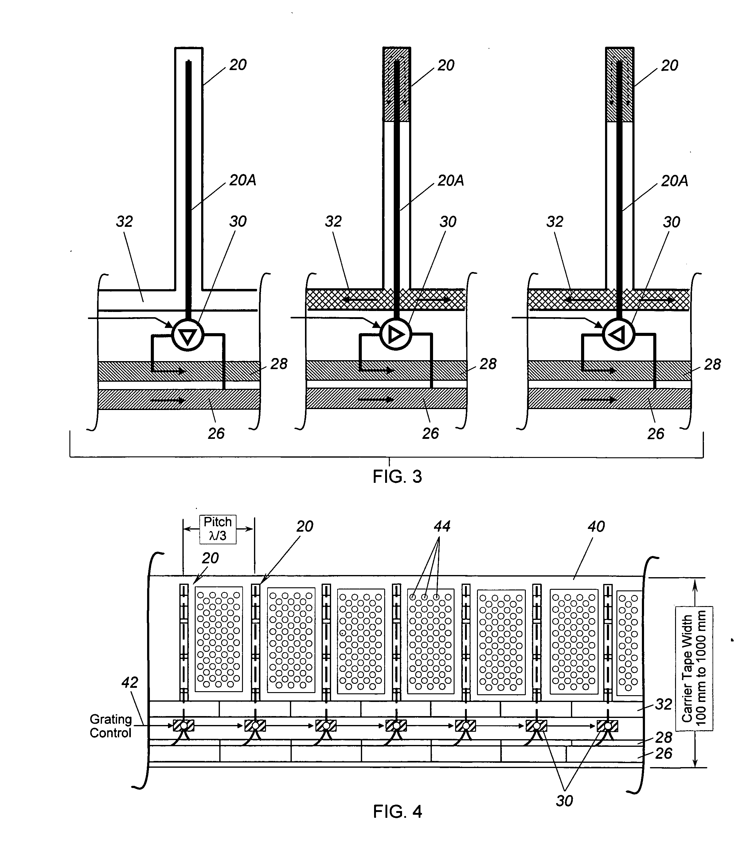
[0020] As shown in the drawings for purposes of illustration, the present invention pertains to the application of holography and diffraction grating principles to radio-frequency (RF) lens type antennas. Basically, an RF lens comprises an array of elements that have the effect of refracting an RF beam, in a manner analogous to the refraction of optical radiation by an optical lens. Although RF lens type antennas have been known for some years, their use in practice has been limited by their known disadvantages of a narrow instantaneous bandwidth, and frequency and directional characteristics that are fixed by the specifics of hardware implementation.

[0021] In accordance with the invention, optical principles of holography and diffractions gratings are applied in the context of RF radiation. As will become apparent from the following description, a holographic device applying the principles of the invention can be conveniently configured to handle multiple RF beams, to null out int...


PUM


Abstract

A three-dimensional holographic array of radio-frequency (RF) diffraction gratings, each of which has lengths of conductive and insulating fluid that are selected and adjusted to provide a desired diffraction effect on incident RF radiation. The three-dimensional array functions analogously to an optical hologram, and is programmable to provide desired refraction and focusing effects on multiple RF incident beams, which may be selectively directed to receivers or, if interferers, ignored. Because the gratings employ conductive and insulating fluids, the array can be reprogrammed in near real time to adapt to changes in the incident RF radiation.

Description

BACKGROUND OF THE INVENTION [0001] This invention relates generally to radio-frequency (RF) antennas and, more particularly, to RF lens type antennas. Optical lens principles have been applied to RF antennas, either as an alternative to or in conjunction with reflective antennas. In simple terms, an RF lens comprises an array of elements that function as waveguides and provide regions of different propagation velocity for incident RF radiation. Therefore, an RF beam is refracted by the lens and can be selectively focused and / or steered as desired. RF lens type antennas have long been recognized for their advantages of high gain and very good interference rejection, but are also known to suffer from significant drawbacks. Specifically, RF lens antennas typically have a narrow instantaneous bandwidth, are limited to a handling single beam, and have a direction and frequency that are fixed by the specific hardware implementation of the lens. Unfortunately, these drawbacks are extremely...

Claims


Application Information

Patent Timeline
IPC IPC(8): H01Q15/02
CPCH01Q19/067
Inventor UPTON, ERIC L.
Owner NORTHROP GRUMMAN SYST CORP
Why Eureka
Try Eureka