Acoustic feedback suppression for audio amplification systems

a technology of acoustic feedback and audio amplification, applied in the direction of transducer casings/cabinets/supports, transducers, electric transducers, etc., can solve the problems of distortion or system instability, unpleasant and sometimes intolerable, and adverse acoustic resonant frequency of audio amplification systems, and achieve the effect of enhancing acoustic feedback suppression

Inactive Publication Date: 2007-05-10
GPE INT
View PDF12 Cites 32 Cited by
  • Summary
  • Abstract
  • Description
  • Claims
  • Application Information

AI Technical Summary

Benefits of technology

[0007] Accordingly, it is an object of this invention to provide means, methods, schemes and / or apparatus for enhanced acoustical feedback suppression for an audio amplification system. More specifically, although not solely limited thereto, it is an object of this invention to provide means and method for acoustical feedback suppression in which an adverse feedback resonant frequency is isolated from a frequency band for subsequent suppression. At a minimum, it is an object of this invention to provide the public with a useful choice of a novel acoustic feedback suppression means and method for application in audio amplification systems.

Problems solved by technology

In an electronic audio amplification system with audio output which can be picked up by the system input, the picking up of an acoustical resonant frequency by the system input can result in undesirable behaviours such as distortion or system instability.
The undesirable behaviours are typically recognizable as howling or whistling which can be unpleasant and sometimes intolerable.
However, it is known that an adverse acoustic resonant frequency of an audio amplification system is dependent on multiple factors such as the relative positioning of microphones and loudspeakers as well as the acoustic properties of a venue, for example, the sound absorption characteristics of a venue and the presence of objects in the acoustic paths.
The suppression of this entire frequency bin results in deterioration of sound quality and is therefore not desirable.

Method used


Image

  • Acoustic feedback suppression for audio amplification systems
  • Acoustic feedback suppression for audio amplification systems
  • Acoustic feedback suppression for audio amplification systems

Examples


Embodiment Construction

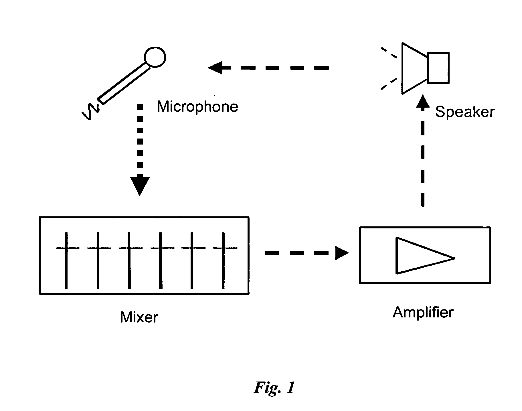
[0049]FIG. 1 shows a typical set-up of an audio amplification system in which the invention of this application finds exemplary applications. The exemplary audio amplification system comprises a microphone as an audio pick-up means, an optional mixer for mixing a variety of audio inputs from a plurality of sources, an audio power amplifier for amplifying the audio signals and a loudspeaker for delivering the amplified audio signals to the audience. During operating of the audio amplification system, audio signals containing an adverse feedback resonant frequency may be delivered by the loudspeakers. This adverse feedback resonant frequency when picked up again by the microphone will develop into howling or other unstable phenomenon in the audio amplification system. To suppress howling, it is desirable that the howling frequency is detected and suppressed before or during audio power amplification for optimized sound output.

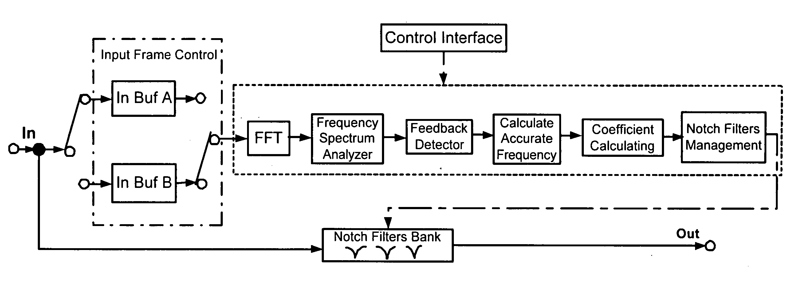
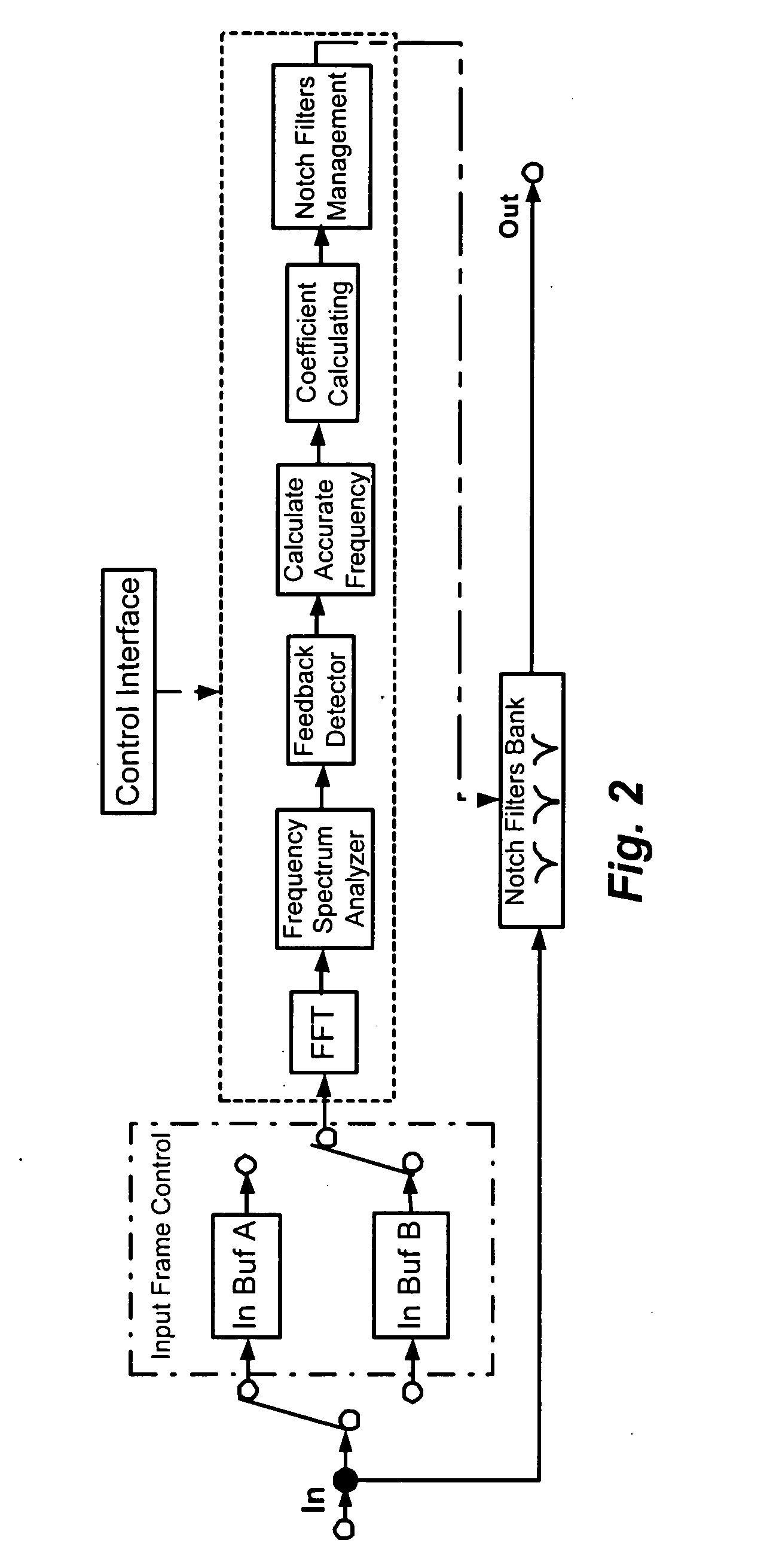
[0050]FIG. 2 is a block diagram illustrating an acoustic f...


PUM


Abstract

In a method of acoustic feedback suppression, digitized time-domain samples of acoustic signals are obtained, and discrete time-frequency transformation is performed on the digitized time-domain samples to generate a plurality of frequency bins of a frequency resolution. A howling frequency bin is identified, where the howling frequency has the maximum magnitude among the plurality of frequency bins. A peak frequency within the howling frequency bin is detected, and this peak frequency is suppressed.

Description

FIELD OF THE INVENTION [0001] This invention relates to acoustical feedback suppression and, more particularly, to acoustical feedback suppression for audio amplification systems. More specifically, this invention relates to acoustical feedback suppression for audio amplification systems with real-time audio input and output such as a PA system. BACKGROUND OF THE INVENTION [0002] In an electronic audio amplification system with audio output which can be picked up by the system input, the picking up of an acoustical resonant frequency by the system input can result in undesirable behaviours such as distortion or system instability. The undesirable behaviours are typically recognizable as howling or whistling which can be unpleasant and sometimes intolerable. Hence, it is desirable that adverse acoustical feedback is suppressed to alleviate, if not eliminate, such undesirable behavior. An example of such audio amplification system is a public address system, a Karaoke system or a conc...

Claims


Application Information

Patent Timeline
Patent Type & Authority Applications(United States)
IPC IPC(8): H04B15/00H04R27/00
CPCH04R3/02H04R27/00
Inventor SHI, YONGSUN, JING
Owner GPE INT
Why Eureka
Try Eureka