Portable medical and cosmetic photon emission adjustment device and method using the same

a technology of photon emission adjustment and medical devices, which is applied in the field of portable medical and cosmetic photon emission adjustment devices, can solve the problems of skin burning, uneven laser beams on the affected parts, and conventional devices that are not widely used in cosmetology

Inactive Publication Date: 2007-05-10
LIN WUN CHEN
View PDF3 Cites 72 Cited by
  • Summary
  • Abstract
  • Description
  • Claims
  • Application Information

AI Technical Summary

Benefits of technology

[0010] It is an object of the present invention to provide a portable medical and cosmetic photon emission adjustment device with the control of dose of photon for use in a certain medical light source. A light source for medical treatment is positioned in a portable device so as to adjust dose of photon emission by a dose adjustment device. The dose adjustment device includes a microprocessor for processing and transmitting control signals and instruction signals. The dose adjustment device is electrically coupled to a configuration controller of the microprocessor to control a plurality of switch devices. Besides, the switch devices include a power switch, a time control switch, a light source control switch and an emission mode switch. The present invention utilizes a chip-on-board manufacturing process to manufacture a light source and includes an emission area adjustment device. The light source can be a high power light-emitting diode (LED) or laser diode and is combined with a set of lenses to achieve light convergence or light diffusion.

Problems solved by technology

However, the laser beams are used as light source to stimulate hair growth by destroying skin tissue.
Because of a thermal effect, wrong manipulation of the light source can cause skin to be burned.
Besides, density of teeth of the emitter results in uneven laser beams on the affected part.
The conventional device is not widely used for cosmetology by individual because the conventional device employing therapeutic light beams is usually applied to big-sized medical instrument or appliance.
Additionally, the conventional device does not control emission area so that it is impossible for the conventional device to control accurately the dose of photon emission.

Method used


Image

  • Portable medical and cosmetic photon emission adjustment device and method using the same
  • Portable medical and cosmetic photon emission adjustment device and method using the same
  • Portable medical and cosmetic photon emission adjustment device and method using the same

Examples


Embodiment Construction

[0022] The following detailed description is of the best presently contemplated modes of carrying out the invention. This description is not to be taken in a limiting sense, and is made merely for the purpose of illustrating general principles of embodiments of the invention. The scope of the invention is best defined by the appended claims.

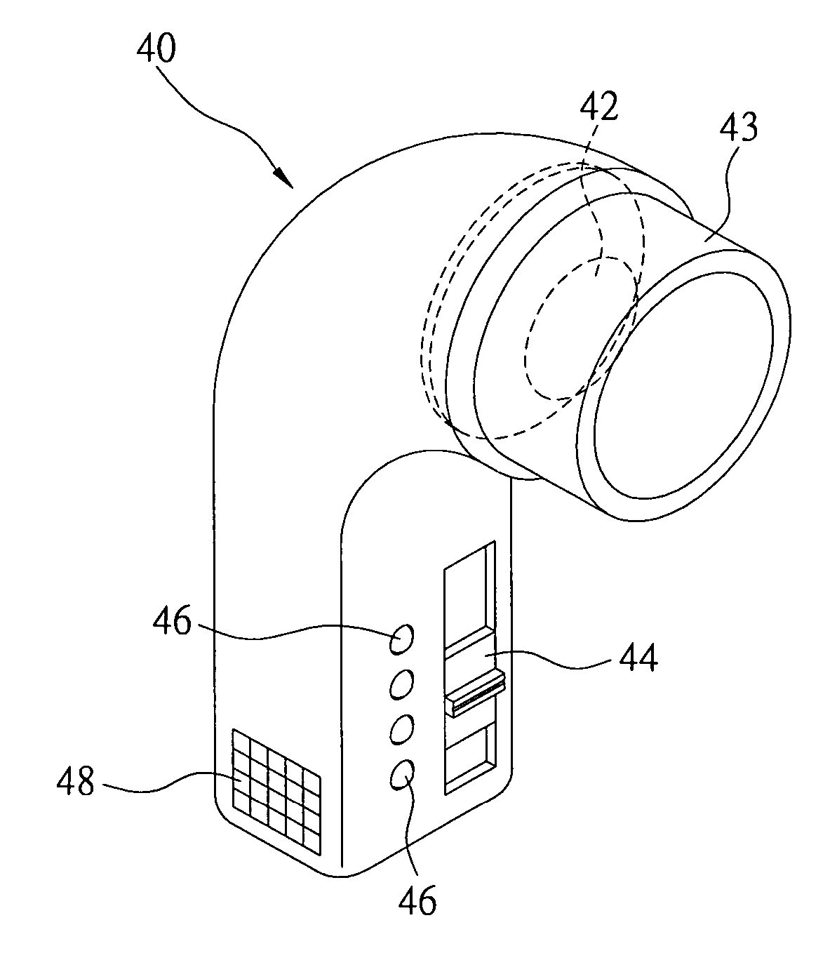
[0023] The present invention provides a portable medical and cosmetic photon emission adjustment device (hereafter referred to as “portable photon emission adjustment device”) and is a hand-held photon emission adjustment device. Besides, the present invention is used to determine a dose of photon emission. The present invention is also used to adjust an emission area adjustment device to change emission area and adjust emission time. The present invention utilizes adjustment of light source to adjust medical and cosmetic doses.

[0024]FIG. 4 schematically illustrates a portable photon emission adjustment device of the present invention. FIG. 4 s...


PUM


Abstract

The present invention describes a portable medical and cosmetic photon emission adjustment device with the control of dose of photon and a method for using the same. A light source for medical treatment is positioned in a portable device to adjust the dose of photon emission by a dose adjustment device. The dose adjustment device has a microprocessor for processing and transmitting control signals and instruction signals. The dose adjustment device is used to control a plurality of light sources. The light source can be a high power light-emitting diode (LED) or a laser diode, and is combined with a set of lenses to achieve light convergence or light dispersion.

Description

BACKGROUND OF THE INVENTION [0001] 1. Field of the Invention [0002] The present invention relates to a portable medical and cosmetic photon emission adjustment device for use in a certain medical light sources, and in particular to adjusting light emission time and light emission area to achieve the control of photon dose for medical and cosmetic purposes. [0003] 2. Description of Related Art [0004] A conventional photomodulation device is widely used in medical treatment and applied to big-sized machines. Fields of application include, for example, cosmetology or treatment of retina disease. [0005] As shown in FIG. 1, animal anomalous tissue is exposed to a matrix-typed light source 10 for medical treatment. The conventional device includes a power supply, a central processing unit (CPU) configured with a variety of light parameters, a protocol for medication, and a probe. The conventional device provides a plurality of light parameters of the light source 10 so that light beams em...

Claims


Application Information

Patent Timeline
Patent Type & Authority Applications(United States)
IPC IPC(8): A61N5/06
CPCA61N5/0617A61N2005/0644A61N2005/0647A61N2005/0651A61N2005/067A61N5/067
Inventor LIN, WUN-CHEN
Owner LIN WUN CHEN
Why Eureka
Try Eureka