
System and Method for Controlling Subsea Wells

a technology for subsea wells and systems, applied in the direction of underwater drilling, survey, borehole/well accessories, etc., can solve the problems of limiting both the power delivered and the ability to optimize operation efficiency, and the substantial power transmission distance can have a deleterious effect on the actual power delivered to the subsea equipment, so as to facilitate improved functionality, reduce latency effects, and enhance the effect of the closed-loop control of the subsea well system

Active Publication Date: 2007-05-17
ONESUBSEA IP UK LTD
View PDF49 Cites 71 Cited by
  • Summary
  • Abstract
  • Description
  • Claims
  • Application Information

AI Technical Summary

Benefits of technology

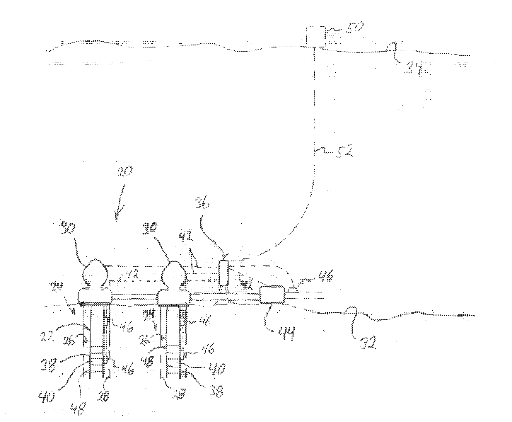
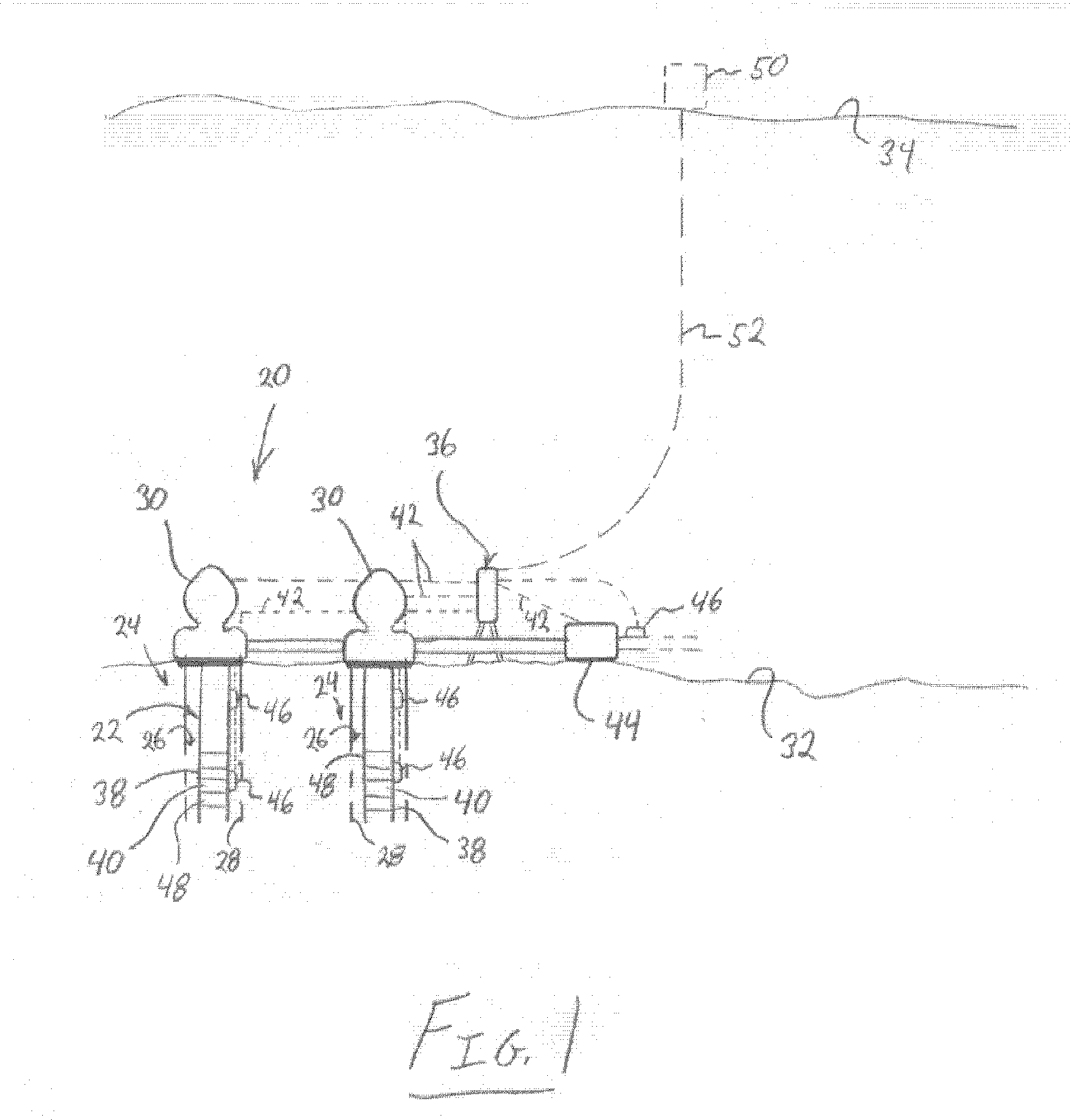
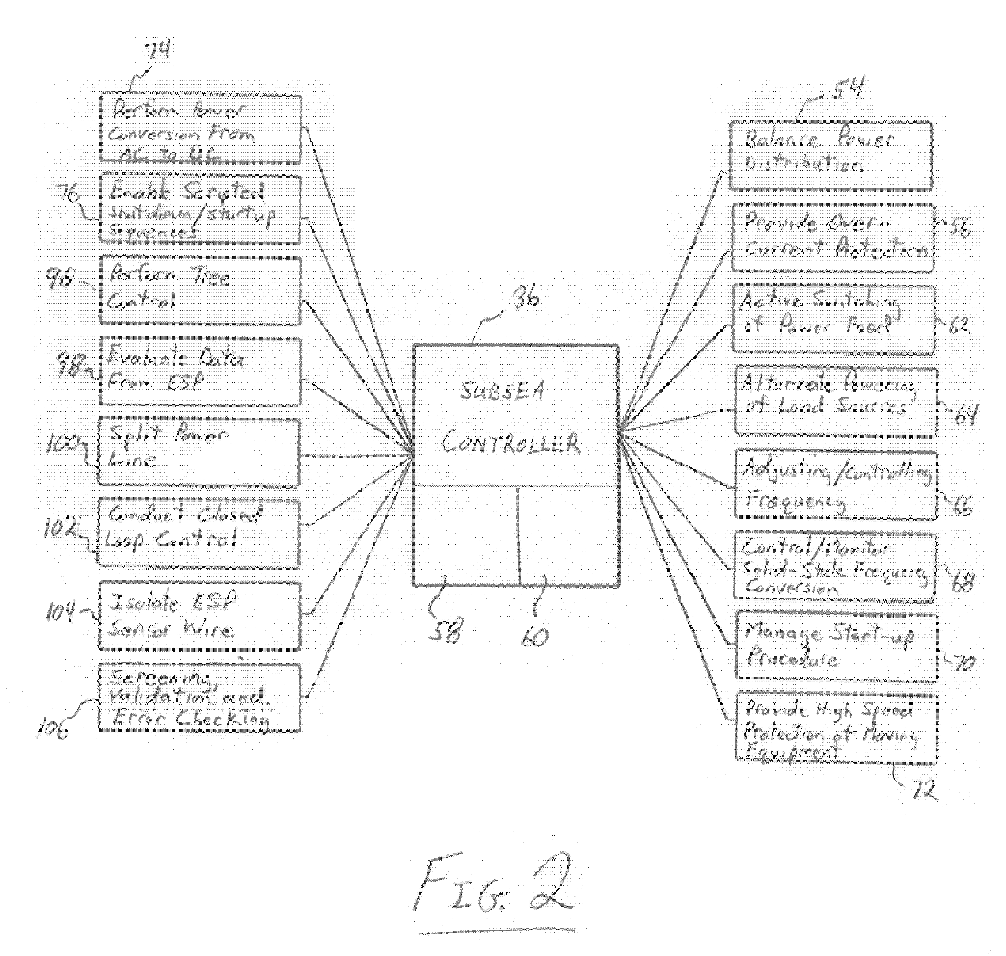
The present invention provides a way to control a subsea well system using a control system located at the subsea level. This helps to reduce delays in controlling the system compared to conventional methods. The control system can manage various components of the well system, such as submersible pumps and booster pumps, and can improve the functioning of the system by balancing power distribution and enhancing control.

Problems solved by technology

The substantial power transmission distances can have a deleterious effect on the power actually delivered to subsea equipment.
The high power requirements combined with the long distances over which power must be transmitted effectively limits both the power delivered and the ability to optimize efficiency of operation with respect to the electric submersible pumping systems, subsea booster pumps and other powered components used in a given subsea production application.

Method used


Image

  • System and Method for Controlling Subsea Wells
  • System and Method for Controlling Subsea Wells
  • System and Method for Controlling Subsea Wells

Examples


Embodiment Construction

[0012] In the following description, numerous details are set forth to provide an understanding of the present invention. However, it will be understood by those of ordinary skill in the art that the present invention may be practiced without these details and that numerous variations or modifications from the described embodiments may be possible.

[0013] The present invention relates to process control operations used in controlling various well equipment. The system and methodology applies process control technology to a subsea well via application of marinized process control equipment that can be positioned subsea at a location more proximate the well equipment of one or more subsea wells. For example, subsea process controllers can be used to control many types of subsea components, including one or more subsea pumps, e.g. subsea booster pumps or subsea submersible pumps used in electric submersible pumping systems. By locating the control system subsea, control of the well equ...


PUM


Abstract

A technique is provided for control of subsea well systems. The technique utilizes a subsea controller coupled to a plurality of subsea well system components to allow localized control of the subsea well system. The subsea controller can be used in a variety of functional applications, such as balancing power distribution to subsea components.

Description

BACKGROUND [0001] In the production of hydrocarbon based fluids, oil and / or gas bearing formations are located and wells are constructed by drilling wellbores into the formations. Appropriate fluid production or other well related equipment is deployed at each well. For example, electric submersible pumping systems can be deployed within each wellbore to produce fluid to a desired collection location. [0002] Many such formations are located beneath the seabed, and well equipment must be moved to subsea positions at or within wellbores formed in the seabed. In many applications, the equipment is deployed at substantial depths and requires the transmission of electrical power over long distances to these subsea positions. The substantial power transmission distances can have a deleterious effect on the power actually delivered to subsea equipment. [0003] With applications using subsea pumps, such as submersible pumps with electric submersible pumping systems and / or subsea booster pump...

Claims


Application Information

Patent Timeline
Patent Type & Authority Applications(United States)
IPC IPC(8): E21B43/36
CPCE21B33/0355E21B43/128E21B41/00E21B43/017
Inventor SMEDSTAD, ERICMACKENZIE, RORYKERR, JOHNSHEPLER, RANDALL A.SINGH, ROHITASHVA
Owner ONESUBSEA IP UK LTD
Learn More