Rear suspension system

a suspension system and rear suspension technology, applied in the direction of resilient suspensions, interconnection systems, vehicle components, etc., can solve the problems of beam and reinforcing member parts where the two connect particularly prone to cracking or breaking, and achieve the effect of enhancing durability

Inactive Publication Date: 2007-05-17
KIA MOTORS CORP
View PDF16 Cites 28 Cited by
  • Summary
  • Abstract
  • Description
  • Claims
  • Application Information

AI Technical Summary

Benefits of technology

[0009] The present invention has been made in an effort to

Problems solved by technology

Portions of the beam and the reinforcing members where the two connect are particularly p

Method used


Image

  • Rear suspension system
  • Rear suspension system
  • Rear suspension system

Examples


Embodiment Construction

[0015] An exemplary embodiment of the present invention will hereinafter be described in detail with reference to the accompanying drawings.

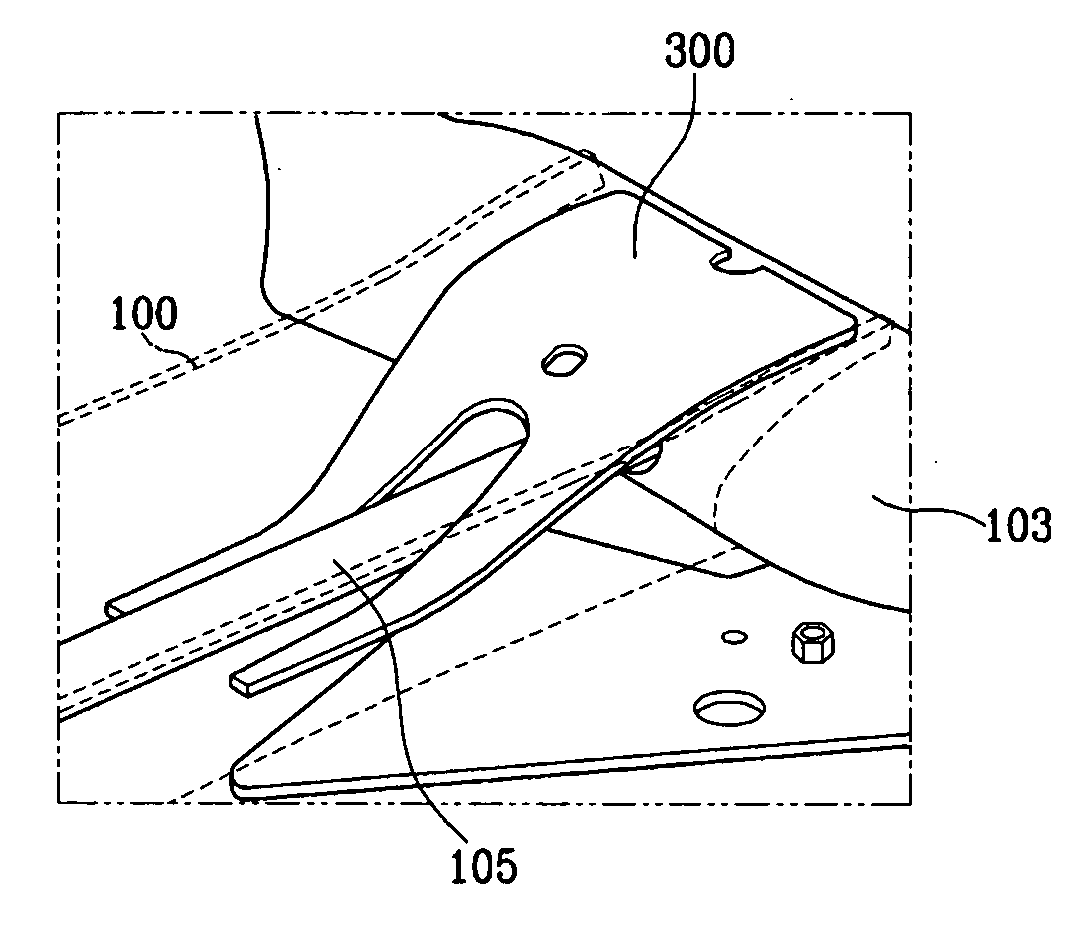
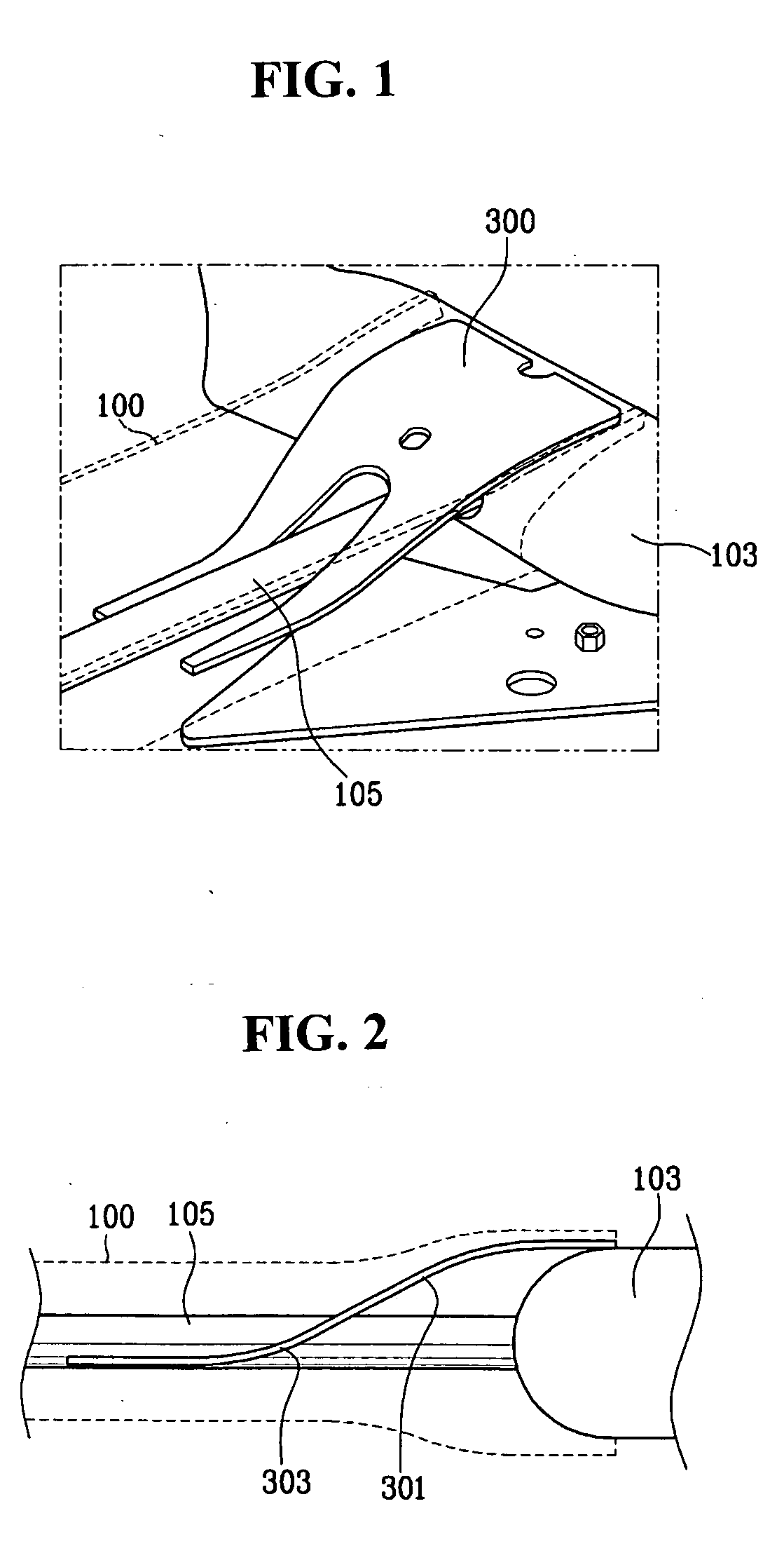
[0016] A rear suspension system according to an exemplary embodiment of the present invention includes a plurality of trailing arms 103, a beam, 100, and a plurality of reinforcing members 300.

[0017] The trailing arms 103 are each connected to a rear wheel (not shown), the beam 100 connects the trailing beams 103 to each other, and the beam 100 defines a space therein.

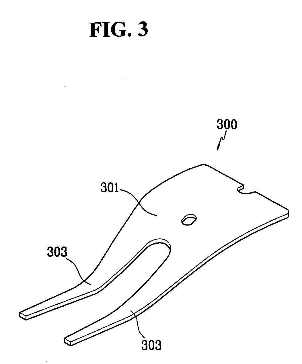
[0018] One end of the reinforcing member 300 is attached to the trailing arm 103, and the other end contacts an interior surface of the beam 100. The reinforcing member 300 includes at least one curved portion 301, 303.

[0019] A rod 105 connecting the trailing arms to each other may be disposed in the space defined within the beam 100. In one embodiment, the rod 105 has a cross-section in the shape of a V.

[0020] In addition, the end of the reinforcing member 300 that contacts t...


PUM


Abstract

A rear suspension system includes a plurality of trailing arms, a beam defining a space therein, and a plurality of reinforcing members, each with a first end connected to a respective one of the trailing arms and a second end contacting an interior surface of the beam. The second end of each reinforcing member is branched into two portions with a rod disposed between them. Each reinforcing member has at least one and preferably two curved portions, one near each end, both curved along the beam axis such that the second end of the reinforcing member is parallel with the rod.

Description

CROSS-REFERENCE TO RELATED APPLICATION [0001] This application claims priority to and the benefit of Korean Patent Application No. 10-2005-0108115 filed in the Korean Intellectual Property Office on Nov. 11, 2005, the entire contents of which are incorporated herein by reference. BACKGROUND OF THE INVENTION [0002] (a) Field of the Invention [0003] The present invention relates to a rear suspension system of a vehicle. More particularly, the present invention relates to a rear coupled torsion beam axle (CTBA) suspension system having enhanced durability. [0004] (b) Description of the Related Art [0005] Generally, a suspension system of a vehicle absorbs shocks transmitted from the road and controls vehicle body dynamics during acceleration, deceleration, and cornering. [0006] A conventional rear suspension system includes a plurality of trailing arms, a rod, a beam, and a plurality of reinforcing members. The rod and the beam connect the trailing arms to each other, and the reinforci...

Claims


Application Information

Patent Timeline
IPC IPC(8): B60G9/00B60G21/05
CPCB60G7/001B60G21/051B60G2200/21B60G2206/014B60G2206/20B60G2206/8103
Inventor KIM, SANG DAELEE, KWANG HO
Owner KIA MOTORS CORP
Why Eureka
Try Eureka