
Air bag with groove or recess, open or partially covered

a technology of air bags and grooves, applied in the direction of pedestrian/occupant safety arrangements, vehicular safety arrangements, vehicle components, etc., can solve the problems of high degree of reliability, high cost and complexity of sensors, and no system commonly used can accommodate deployment, etc., to achieve high reliability and avoid significant cost penalties

Inactive Publication Date: 2007-05-17
KEY SAFETY SYST
View PDF20 Cites 64 Cited by
  • Summary
  • Abstract
  • Description
  • Claims
  • Application Information

AI Technical Summary

Benefits of technology

[0011] An air bag system according to the present invention can perform without requiring vehicle occupant weight or position sensors.
[0012] The air bag design of the present invention is such that it achieves an inherent very high reliability without any significant cost penalty.

Problems solved by technology

These sensors are costly and very sophisticated and require a very high degree of reliability to insure they function over the life of a vehicle.
To date none of the systems commonly used can accommodate the deployment of an air bag towards an infant in an infant seat located upon the front seat of a vehicle and facing the rear of a vehicle.
The use of the above system leads to high loads being created against the out-of-position occupant.
These and other factors make the design and construction of such safety devices very complex while no other device, other than the seat belt, is credited with saving more lives and minimizing the occurrence of serious injury.
In science and engineering a constant truth is that “simplicity leads to reliability.” The trend toward complex sensors and controls increases the number of components, which inherently leads to increasing the risk of a component malfunction that reduces the overall reliability.
To avoid this problem engineers are forced to design in redundancy, which further drives up cost.

Method used


Image

  • Air bag with groove or recess, open or partially covered
  • Air bag with groove or recess, open or partially covered
  • Air bag with groove or recess, open or partially covered

Examples


Embodiment Construction

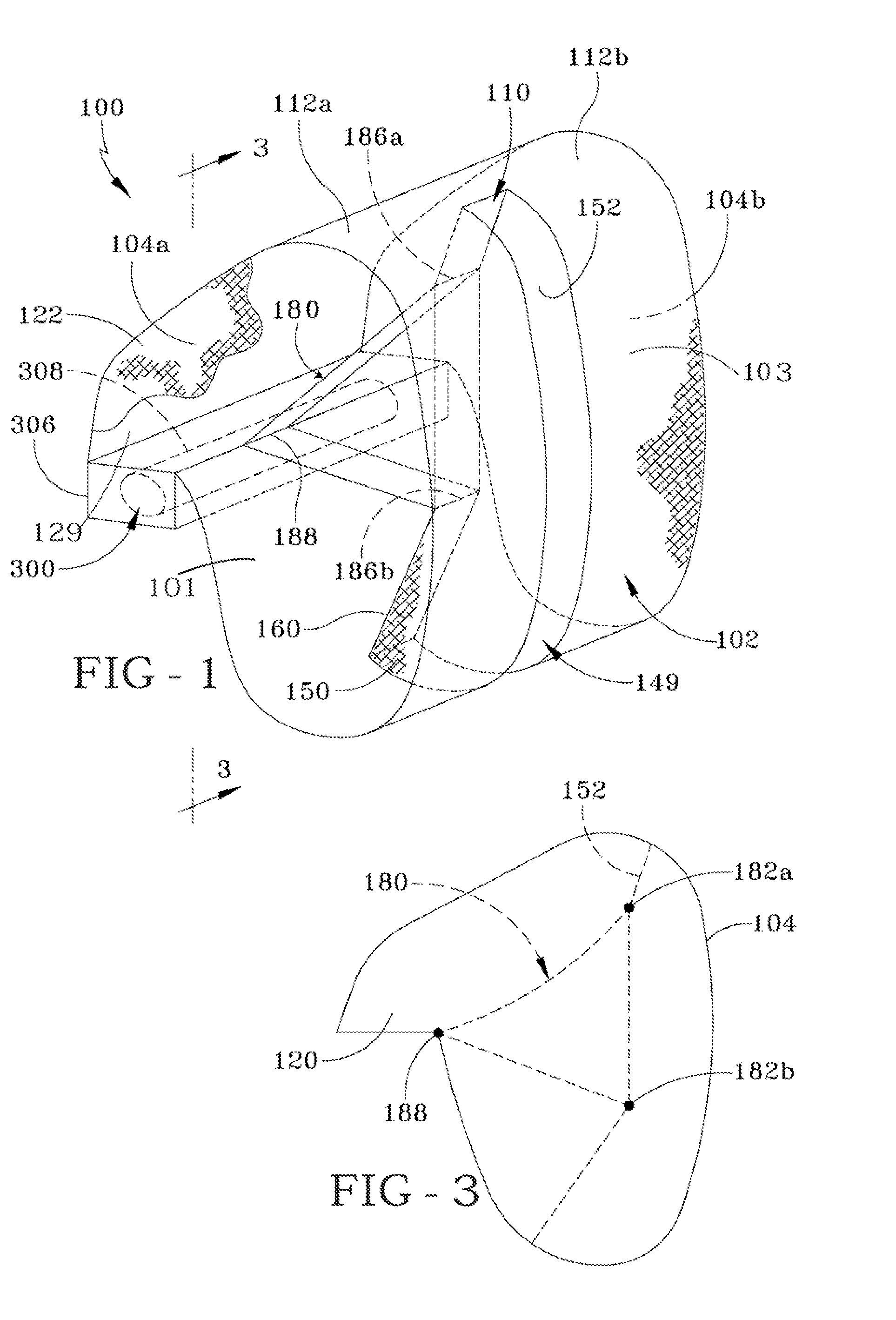
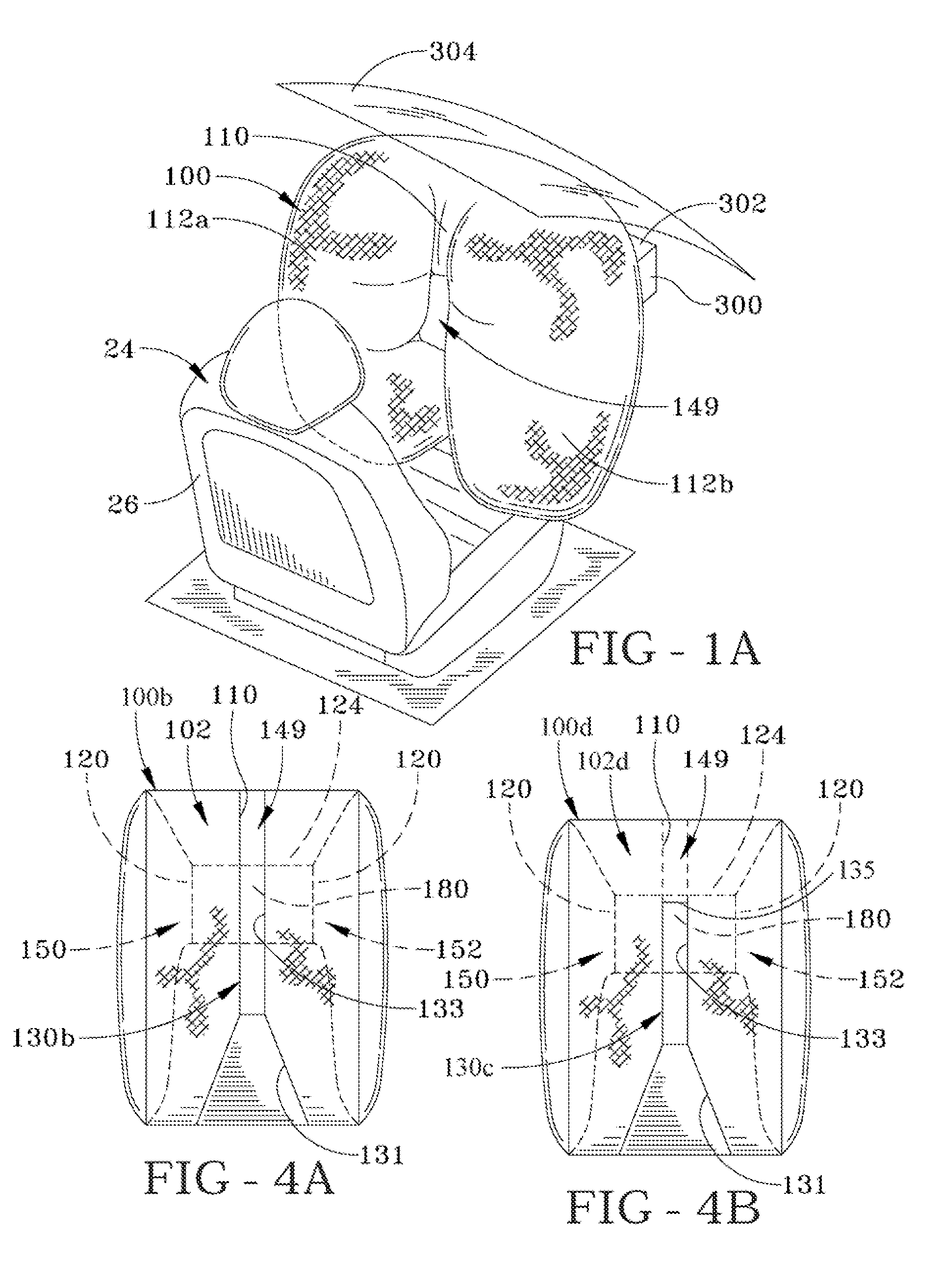
[0038] The air bag shown in various figures has a single chamber 101 and in general can be formed by one or more panels of fabric. The air bag can be woven or knitted as a one-piece construction or formed by sewing or bonding a plurality of panels together. A groove 110 is formed behind the panel or portion of the air bag facing the occupant to be protected. In the illustrated embodiment, air bag 100 includes a main panel 102 having a face panel portion 103, which faces the vehicle occupant to be protected, and a plurality of side panels 104a, 104b. As can be appreciated the size of the air bag and its various panels will change in each vehicular application. Further, as can be appreciated it is not necessary to form the air bag with separate side panels and a linking main (or center) panel. Each of these panels is typically made from woven fabric comprising nylon or polyester. The side panels 104a, 104b are substantially identical and are the mirror image of each other. Each of the...


PUM


Abstract

An air bag (100) has an inflatable chamber (101,301) defined by a main front panel (102, 212) and a pair of side panels (104a, b; 224, 226). The air bag (100) has a vertically oriented recessed portion (110, 220) spanning along most of the length of the main panel or a limited section thereof. The recessed portion (110, 220) divides the air bag (100, 210) into two lower lobe portions (112a,b, 240, 242) on each side of the recessed portion. Upon inflation an internal tether (180, 250) is attached to the recessed portion and is anchored at or adjacent to the gas inlet passageway thereby limiting forward movement of the recessed portion upon inflation. The air bag is useful as a frontal air bag, particularly a passenger frontal air bag.

Description

RELATED APPLICATIONS [0001] This application claims the benefit of U.S. Provisional Application 60 / 790,185, filed on Apr. 7, 2006 and is a Continuation in Part of U.S. patent application Ser. No. 11 / 252,426 filed on 17 Oct. 2005 entitled “Grooved Air Bag” and Continuation in Part of U.S. patent application Ser. No. 11 / 341,791 filed Jan. 28, 2006 entitled “Air Bag with a Strategically Placed Recess.”SUMMARY AND BACKGROUND OF THE INVENTION [0002] This invention primarily relates to passenger side air bags deployed from an instrument panel of a vehicle. [0003] As shown in prior art FIG. 13, a conventional passenger side air bag 20 is inflated by an air bag inflator 280. The air bag 20 typically has a single inflatable chamber 330 inflated by gas from the inflator 280. The face portion or front panel 320 of the air bag 20 impacts the vehicle occupant 22 across the chest, shoulders and head. As the vehicle occupant assumes a seated position closer to the vehicle's instrument panel and aw...

Claims


Application Information

Patent Timeline
Patent Type & Authority Applications(United States)
IPC IPC(8): B60R21/233B60R21/23B60R21/231B60R21/2338
CPCB60R21/231B60R21/233B60R21/2338B60R21/272B60R2021/0004B60R2021/0044B60R2021/23324B60R2021/23382B60R2021/23386
Inventor PANG, HYUNSOKKIM, SOONSIKCOON, JEFFREY S.
Owner KEY SAFETY SYST
Features
  • Generate Ideas
  • Intellectual Property
  • Life Sciences
  • Materials
  • Tech Scout
  • Unparalleled Data Quality
  • Higher Quality Content
  • 60% Fewer Hallucinations
Learn More