
Chair

Inactive Publication Date: 2007-05-17
KOKUYO CO LTD
View PDF70 Cites 21 Cited by
  • Summary
  • Abstract
  • Description
  • Claims
  • Application Information

AI Technical Summary

Benefits of technology

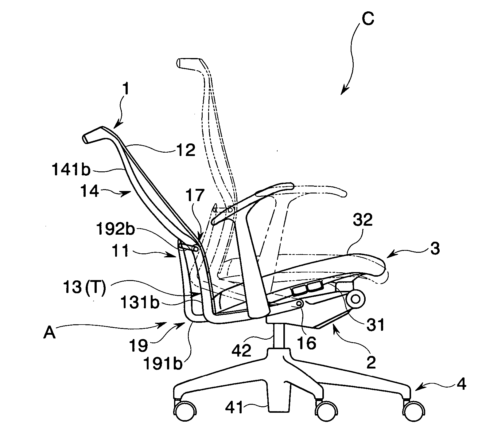
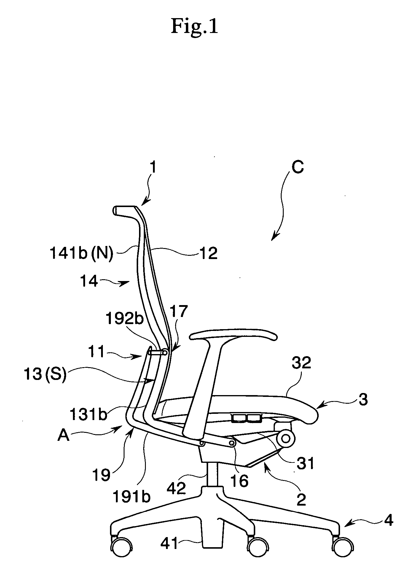
[0010] With such an arrangement, it is possible to set the movement range of the upper frame portion to meet the posture of a seating person, and particularly a posture of the upper body. More particularly, where it is desired to make the shape of the backrest of the chair follow movements of the upper body of a seating person, the movement range of the upper frame portion can be set large while when the backrest is required to support the upper body of the seating person, the movement range of the upper frame portion can be set small. As a result, it is possible to provide a chair having a backrest that is capable of exhibiting functions as desired by a seating person.
[0011] For achieving an arrangement in which movements of the upper body are not prevented when the upper body of a seating person is upright as well as an arrangement with which the upper frame portion can preferably support the upper body of the seating person when the upper body is inclining backwards, a movement range setting mechanism is desirably arranged in that the movement range of the upper frame portion is set to become narrower in accordance with the lower frame portion coming closer to the rearward tilting position. Here, the reduced movement range also includes an aspect in which the backrest is immovably fixed.
[0017] By employing the frame-like spring and by arranging the same to face along other frame elements that comprise the back frame portion, the entire chair can be arranged in a compact manner. Particularly in case a “frame-like” spring corresponding to the shape of the frame elements is employed, it is possible to arrange an upper frame portion elastically biasing means that is indistinctive as an entire chair. Moreover, with a frame-like spring, it is possible to arrange an elastic member that exhibits preferable elastically biasing force also in the above-mentioned case in which it is provided between the base and the upper frame portion that are remote from each other with the lower frame portion being interposed between.
[0020] According to the present invention, where it is desired to make the shape of the backrest of the chair follow movements of the upper body of a seating person, the movement range of the upper frame portion can be set larger while when it is desired to make the backrest support the upper body of the seating person, the movement range of the upper frame portion can be set narrower. As a result, it is possible to provide a chair having a backrest capable of achieving functions that are in accordance with postures of a seating person.

Problems solved by technology

More particularly, when the upper frame element of the backrest is movable in accordance with movements of the upper body of the seating person as discussed above, it will in turn be impossible to support the upper portion of the upper body in a stable manner.
Such an arrangement will cause a drawback in that the seating person might feel unstable when he or she inclines his or her upper body to incline the lower frame element of the backrest backward.

Method used


Image

  • Chair
  • Chair
  • Chair

Examples


first modified example

[0070] It is, for instance, possible to provide a switching mechanism SW for temporality terminating functions of the above-mentioned movement range setting mechanism A as shown in FIG. 13. More concretely explaining, a folding portion 193b is provided proximate of the contacting end portions 191a1, 191b1 of the regulating members 191a, 191b, and by suitably rotating the folding portion 193b, it is possible to switch between an ON condition (ON) in which the contacting end portions 191a1, 191b1 may abut the upper frame elements 141a, 141b and an OFF condition (OFF) in which the butting end portions 191a1, 191b1 may not abut the upper frame elements 141a, 141b as indicated by the dotted line.

[0071] Further, as illustrated in FIG. 14, it is also possible to provide a projecting and sinking regulating portion 194b in the vicinity of the contacting end portions 191a1, 191b1 of the regulating members 191a, 191b, wherein by suitably operating the projecting and sinking regulating portion...

second modified example

[0073] It is further possible to further provide an upper frame portion elastically biasing means X1 that elastically biases the upper frame portion 14 from the rear end position (E) to the normal position (N) as illustrated in FIGS. 15 and 16. More particularly, the upper frame portion elastically biasing means X1 is arranged in that elastically biasing force applied to the upper frame portion 14 is set to be larger with the lower frame portion 14 coming closer to the rearward tilting position (T) In other words, as shown in the drawings, the upper frame portion elastically biasing means X1 is mainly comprised of a torsion coil spring 17sp that serves as the elastic member provided between the upper frame portion 14 and the lower frame portion 13, that is, in the vicinity of the hinge 17, wherein one end 171sp of the torsion coil spring 17sp is fixed to the upper frame elements 141a, 141b while the other end 172sp is fixed to the link elements 192a, 192b. When the lower frame porti...

third modified example

[0075] As shown in FIGS. 17 and 18, it is possible to arrange an upper frame portion elastically biasing means X2 as an elastic member by providing a reaction frame portion 15 between the base 2 and the upper frame portion 14.

[0076] The reaction frame portion 15 is comprised of a number of reaction frame elements 151a, 151b corresponding to a number with which each of the upper frame elements 141a, 141b can be supported. One end portion of the reaction frame elements 151a, 151b are joined to the rear surface of the upper frame elements 141a, 141b while the other end is joined to the base 2. The reaction frame elements 151a, 151b might, for instance, be elastic bodies made of the same material resin as the elastic lateral bridging member 142. In the present embodiment, the reaction frame elements 151a, 151b are frame-like resin springs having a substantially L-shaped form extending along the lower frame elements 131a, 131b and the upper frame elements 141a, 141b when seen from a sid...


PUM


Abstract

It is a subject to provide a chair capable of realizing a condition in which movements of a seating person are preferably followed and a condition in which a back of the seating person can be preferably supported. For this purpose, a chair C comprising a lower frame portion that is supported to be rockable between a standing position and a rearward tilting position of a back frame with respect to the base and an upper frame portion that is supported to be rockable between a normal position and a rear end position, wherein the chair is further comprised with a movement range setting mechanism with which a movement range through the rocking movement of the upper frame portion with respect to the lower frame portion is made changeable in accordance with the position of the lower frame portion with respect to the base during the rocking movement.

Description

BACKGROUND OF THE INVENTION [0001] 1. Field of the Invention [0002] The present invention relates to a chair which a backrest can be inclined backwards. [0003] 2. Description of the Related Art [0004] A chair which a backrest surface is arranged by bridging an upholstery member between frame elements that comprise a pair on the right and left sides is conventionally disclosed. For instance, there is disclosed a chair arranged in that an upper portion of the backrest surface is supported by an upper frame element while a lower portion of the backrest surface is supported by the lower frame element, wherein each of the upper frame element and the lower frame element is individually made to perform rotating operations around a horizontal axis, that is, rocking operations (see, for instance, Japanese Patent Laid-Open Publication No. 2002-119375 and Japanese Patent Laid-Open Publication No. 2002-119373). With this arrangement, such chairs realize the backrest surface that suits trunks or...

Claims


Application Information

Patent Timeline
IPC IPC(8): A47C1/024
CPCA47C1/03255A47C1/03261
Inventor UEDA, NOBUYUKI
Owner KOKUYO CO LTD
Learn More