Direction finder antenna

a technology of direction finder and antenna, which is applied in the direction of antenna, antenna details, collapsible antennas, etc., can solve the problems of directional error, inability to make the effective height of the antenna so high, and difficulty in always receiving

Inactive Publication Date: 2007-05-17
GEN RES OF ELECTRONICS
View PDF4 Cites 14 Cited by
  • Summary
  • Abstract
  • Description
  • Claims
  • Application Information

AI Technical Summary

Benefits of technology

[0030] According to the direction finder antenna according to another aspect of the present invention as well, the direction finder antenna is brought to such a structure that the flat portion of the antenna mount is configured as the antenna upright-provided surface, the extensible whip antenna elements of four or more respectively upright provided rotatably at the antenna upright-provided points formed on the antenna upright-provided surface are provided, and the extensible whip antenna elements can respectively be set rotatably to the arbitrary angular positions in the hemispherical areas formed on the antenna upright-provided surface side, lying in the spherical areas with the respective antenna upright-provided points at the antenna upright-provided surface as the centers. Therefore, the direction finder antenna can bring about advantageous effects in that the tilt angles of the extensible whip antenna elements of three or more and/or their lengths are arbitrarily changed depending upon the frequency of incoming radio waves and the state of polarization thereof to thereby make it possible to more freely select conditions optimum for the frequency of the incoming radio waves and the plane of polarization thereof respectively, whereby the direction of incoming radio waves lying in a very high frequency band and an ultra high frequency band can be detected accurately regardless of whether the incoming radio waves are horizontally polarized waves or vertically polarized waves, and the direction finder antenna is compact in structure and usable in portable form.
[0031] Further, according to the direction finder antenna according to a further aspect of the present invention, the direction finder antenna is brought to such a structure that the side surface portions of the antenna mount are configured as the antenna upright-provided surfaces, the plurality of extensible whip antenna elements respectively upright provided rotatably at the antenna upright-provided points formed on the antenna upright-provided surfaces are provided, and the plurality of extensible whip antenna elements can respectively be set rotatably to the arbitrary angular positions lying in the sector-shaped areas each having the open angle of 180° orthogonal to the straight line connecting the respective antenna upright-provided points formed on the antenna upright-provided surfaces sides centering on the respective antenna upright-provided points at the antenna upright-provided surfaces. T...

Problems solved by technology

The loop antenna is easy to cause a directional error depending on the state of polarization of incoming radio waves and cannot be made so high in antenna effective height.
It is however difficult to always receive, in a satisfactory state, radio waves which are transmitted from a large number of...

Method used


Image

  • Direction finder antenna
  • Direction finder antenna
  • Direction finder antenna

Examples


first preferred embodiment

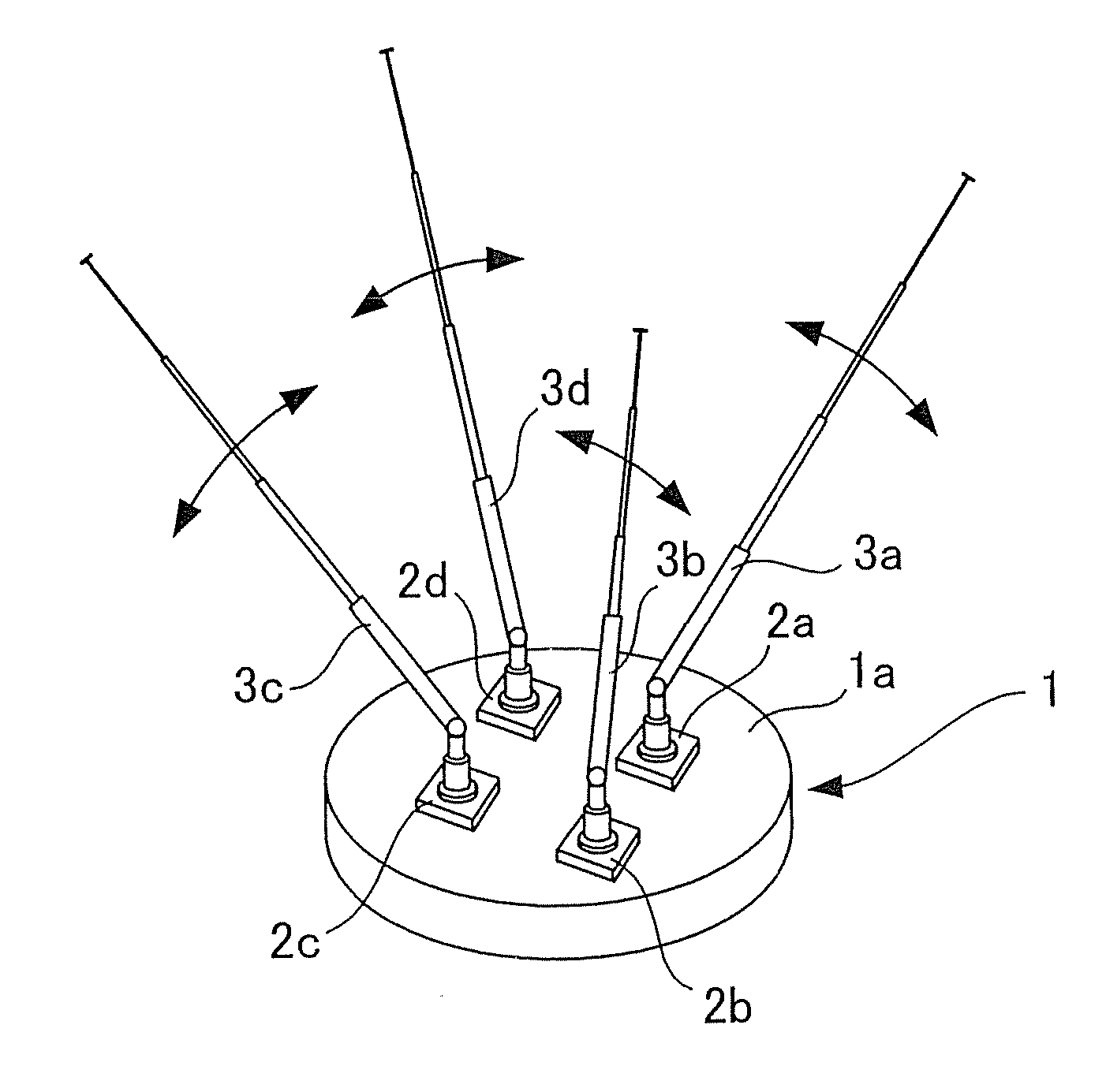
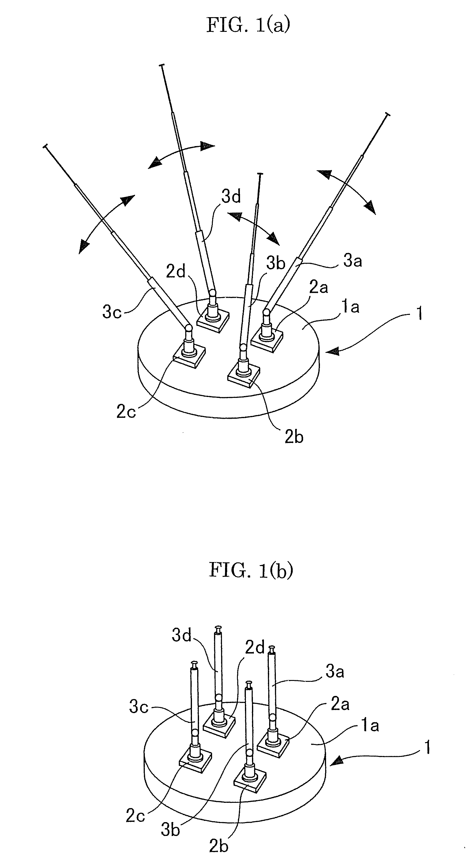
[0041] FIGS. 1(a) and 1(b) show a first embodiment of a direction finder antenna according to the present invention and are perspective views each illustrating a configuration of its essential part, wherein FIG. 1(a) shows the state of four extensible whip antenna elements at the time that their lengths and their tilt angles are respectively adjusted to the optimum state with respect to incoming radio waves, and FIG. 1(b) shows the state of the four extensible whip antenna elements at the time that they are respectively adjusted to their shortest lengths and upstanding angles.

[0042] As shown in FIGS. 1(a) and 1(b), the direction finder antenna according to the first embodiment comprises an antenna mount 1 disc-shaped and formed with a flat or plane portion 1a on one main surface thereof, four antenna holding portions 2a, 2b, 2c and 2d disposed on the flat portion 1a and formed with slide bearings, and four extensible whip antenna elements 3a, 3b, 3c and 3d respectively held by the ...

second preferred embodiment

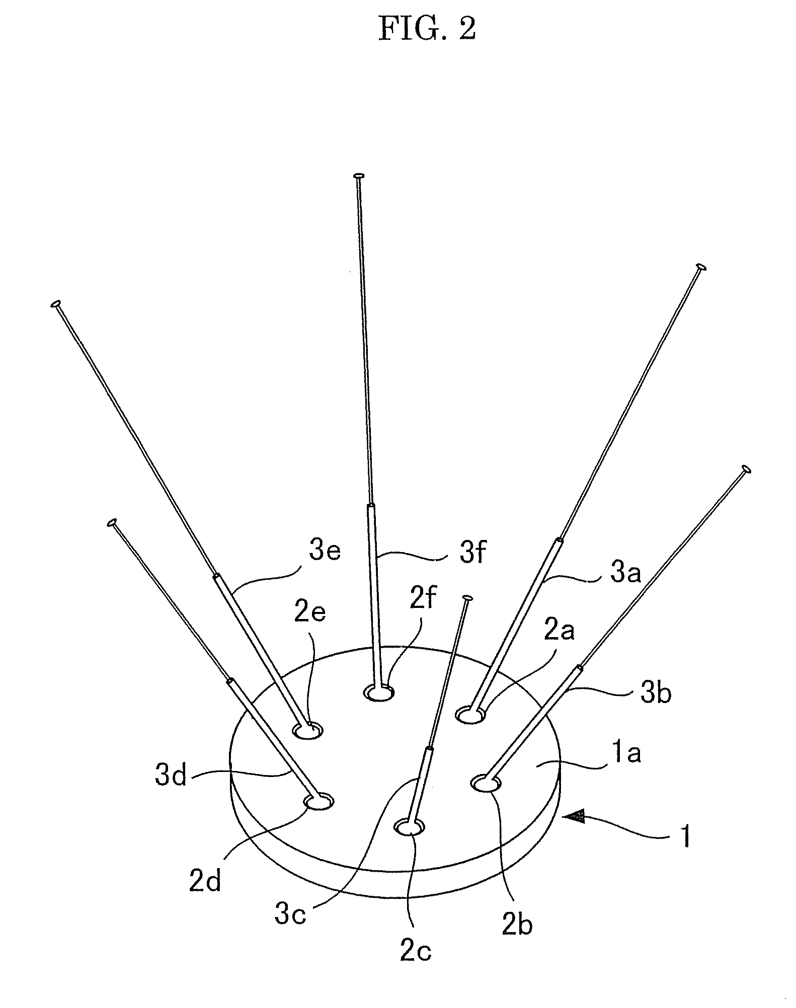
[0049] Next, FIG. 2 shows a second embodiment of a direction finder antenna according to the present invention and is a perspective view illustrating a configuration of its essential part. FIG. 2 shows an example in which six extensible whip antenna elements are upright provided on a flat portion.

[0050] As shown in FIG. 2, the direction finder antenna according to the second embodiment comprises an antenna mount 1 disc-shaped and formed with a flat portion 1a at one main surface thereof, six antenna holding portions 2a, 2b, 2c, 2d, 2e and 2f which are disposed on the flat portion 1a and constitute slide bearings, and six extensible whip antenna elements 3a, 3b, 3c, 3d, 3e and 3f respectively held by the antenna holding portions 2a, 2b, 2c, 2d, 2e and 2f and upright provided rotatably on the flat portion 1a. Even in this case, the six antenna holding portions 2a, 2b, 2c, 2d, 2e and 2f are disposed at equal intervals on one circumference formed on the flat portion 1a. The ranges in w...

third preferred embodiment

[0055] Next, FIGS. 3(a) and 3(b) respectively relate to a third embodiment of a direction finder antenna according to the present invention and shows a configuration of its essential part. The figures show an example using four extensible whip antenna elements. FIG. 3(a) is a perspective view showing a state in which the four extensible whip antenna elements are aimed in the same upper direction and their lengths are extended relatively long, and FIG. 3(b) is a top view showing a state in which the four extensible whip antenna elements are aimed in the same upper direction. In FIG. 3(b), an illustration of the four extensible whip antenna elements is omitted.

[0056] FIGS. 4(a), 4(b) and 4(c) are respectively perspective views showing the states of changes in the extensible whip antenna elements of the direction finder antenna according to the third embodiment, wherein FIG. 4(a) shows an example in which the four extensible whip antenna elements are aimed in the same upper direction ...


PUM


Abstract

The present invention provides a direction finder antenna that includes an antenna mount having one flat portion and four extensible whip antenna elements respectively upright provided rotatably at antenna upright-provided points formed on one circumference at an antenna upright-provided surface. The four extensible whip antenna elements can be rotatably set to arbitrary angular positions lying in sector-shaped areas each having an open angle of 180° orthogonal to the one circumference, which are formed on the antenna upright-provided surface side, centering on the respective antenna upright-provided points at the antenna upright-provided surface.

Description

RELATED / PRIORITY APPLICATION [0001] This application claims priority with respect to Japanese Application No. 2005-327511, filed Nov. 11, 2005. BACKGROUND OF THE INVENTION [0002] 1. Field of the Invention [0003] The present invention relates to a direction finder antenna, and particularly to a direction finder antenna transportable in a compact structure, capable of responding to incoming radio waves lying in a wide frequency range and detecting the direction of the incoming radio waves regardless of the plane of polarization of the radio waves. [0004] 2. Description of the Related Art [0005] As direction finder antennas each used in a direction finder, a loop antenna-series one and an Adocock antenna-series one have heretofore been used principally. As antennas that belong to these series, there have been known those of various forms respectively. [0006] Meanwhile, the loop antenna is of an antenna firstly used as the direction finder antenna. The sensitivity of the loop antenna be...

Claims


Application Information

Patent Timeline
IPC IPC(8): H01Q21/00
CPCH01Q21/062
Inventor TAKAHASHI, TERUO
Owner GEN RES OF ELECTRONICS
Why Eureka
Try Eureka