
Virtual space rendering/display apparatus and virtual space rendering/display method

a virtual space and display apparatus technology, applied in the field of virtual space rendering/display apparatus and virtual space rendering/display method, can solve the problems of limited field of view (field angle) of the viewpoint position on the 3d virtual space, user's inability to easily recognize the current location of the viewpoint position on the 3d, and the viewpoint position cannot be moved in the direction of the obstacl

Inactive Publication Date: 2007-05-17
CANON KK
View PDF9 Cites 53 Cited by
  • Summary
  • Abstract
  • Description
  • Claims
  • Application Information

AI Technical Summary

Benefits of technology

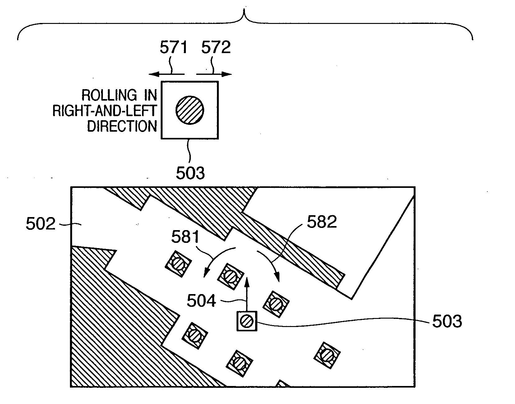
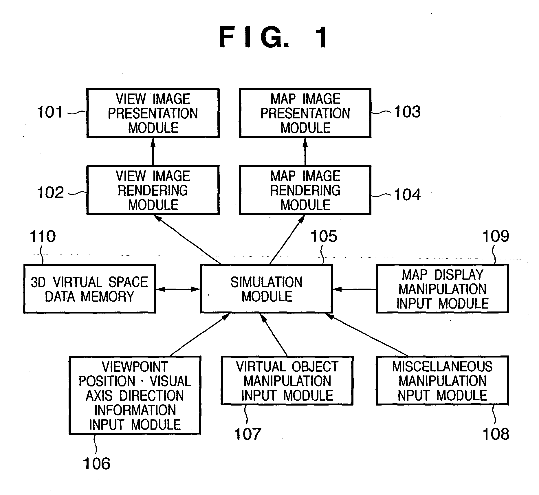
[0013] That is, a virtual space rendering/display method comprising: a first generation step of generating an image of a virtual space on the basis of a first viewpoint indicating a viewpoint of a user on the virtual space; a second generation step of generating a map image indicating a region around a position of the first viewpoint on the virtual space; a viewpoint position•visual axis direction control st

Problems solved by technology

However, according to the conventional method, the field of view (field angle) from the viewpoint on the 3D virtual space is limited, and the user cannot easily recognize the current location of the viewpoint position on the 3D virtual space on the 2D view window.
However, if the viewpoint collides against an obstacle during walkthrough, the viewpoint position can no longer be moved in the direction of the obstacle.
In such case, since the obstacle often falls outside the field of view depending on its position, the user cannot often recognize why he or she cannot change the viewpoint position.
If another manipulative object is present between the position of the virtual object to be manipulated and the viewpoint position, it is difficult to manipulate that virtual object.

Method used


Image

  • Virtual space rendering/display apparatus and virtual space rendering/display method
  • Virtual space rendering/display apparatus and virtual space rendering/display method
  • Virtual space rendering/display apparatus and virtual space rendering/display method

Examples


first embodiment

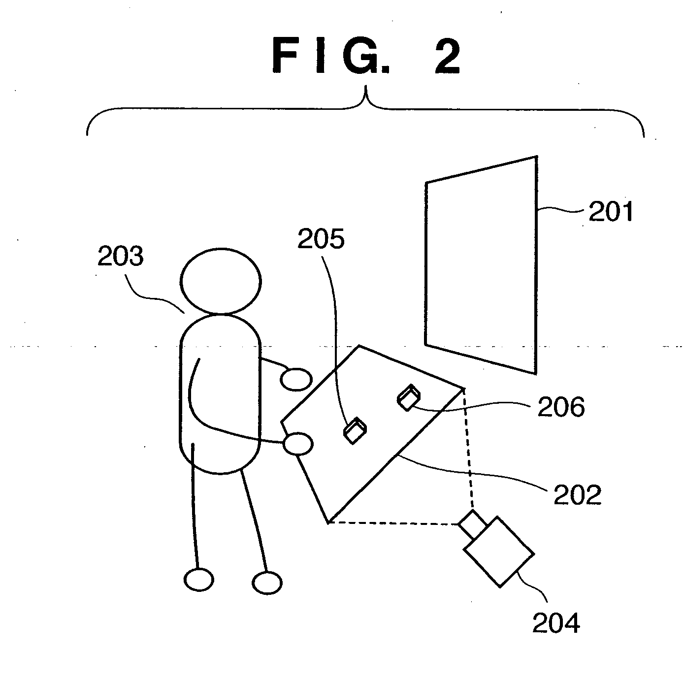
[0044] A virtual space rendering / display apparatus according to this embodiment, which allows the user to experience a 3D virtual space, i.e., to experience walkthrough on the 3D virtual space and manipulation of a virtual object will be described first. Note that walkthrough is that the user browses the 3D virtual space by moving his or her viewpoint position, visual axis direction, and the like on the 3D virtual space.

[0045] The virtual space rendering / display apparatus according to this embodiment generates an image of the 3D virtual space using 3D virtual space data described in VRML. The apparatus generates a view image of the virtual space to be observed by the user in correspondence with the user's viewpoint position and visual axis direction on the virtual space, and a view image presentation device presents that image.

[0046] In order to allow the user to easily recognize his or her current position (viewpoint position) on the virtual space, an input device used to input t...

second embodiment

[0112] In the virtual space rendering / display apparatus according to the first embodiment, the viewpoint position•visual axis direction input UI is fixed in position with respect to the map image display screen, and the map image scrolls or rotates upon walkthrough. Also, the virtual object manipulation input UI is fixed in position with respect to the map image display screen.

[0113] In a virtual space rendering / display apparatus according to this embodiment, the viewpoint position•visual axis direction input UI is movable on the map image display screen. Also, the virtual object manipulation input UI is movable on the map image display screen, while the map image is fixed in position. The user moves the virtual object manipulation input UI to a position near a virtual object and selects that virtual object. When the user manipulates the virtual object manipulation UI while the virtual object is selected, the virtual object is displayed to follow the UI.

[0114] The functional arran...


PUM


Abstract

A view image rendering module (102) generates an image of a virtual space on the basis of a first viewpoint indicating the viewpoint of a user on the virtual space, and displays the generated image on a view image presentation module (101). A map image rendering module (104) generates a map image indicating a region around the position of the first viewpoint on the virtual space, and displays the generated map image on a map image presentation module (103). The position of the first viewpoint and the visual axis direction are controlled using a viewpoint position•visual axis direction input module (106) which is provided on the display surface of the map image presentation module (103). Furthermore, a virtual object set on the virtual space undergoes manipulation control using a virtual object manipulation input module (107) which is provided on the display surface of the map image presentation module (103).

Description

FIELD OF THE INVENTION [0001] The present invention relates to a virtual space rendering / display apparatus and virtual space rendering / display method, which allow a user to experience a virtual space. BACKGROUND OF THE INVENTION [0002] Three-dimensional (3D) computer graphics (CG) techniques have rapidly prevailed along with the improvement of performance of recent computers. In combination with such techniques, VRML (Virtual Reality Modeling Language) has been standardized and widely used as a language that handles a 3D virtual space. The latest VRML2.0 (ISO / IEC 14772-1: 1997) which is open to the public at this time is used to construct a virtual mall for electronic commerce, to manage 3D data for CAD or the like on an intranet, and the like. [0003] The user observes an image on a 3D virtual space described in VRML or the like in accordance with the viewpoint position or visual axis direction set in the virtual space using a two-dimensional (2D) view window. More specifically, the...

Claims


Application Information

Patent Timeline
IPC IPC(8): G06T15/00G06F3/00G06F3/048G09G5/00G09G5/34G09G5/36H04N13/04
CPCG06F3/04815G06T19/00G06T19/003G06T2219/028
Inventor SAKAGAWA, YUKIOKATAYAMA, AKIHIROSUZUKI, MASAHIRO
Owner CANON KK
Learn More