Method and base station for bandwidth allocation in wireless single-hop self-backhaul networks

a wireless self-backhaul and wireless self-backhaul technology, applied in the field of wireless communication networks, can solve the problems of destroying the bandwidth fairness of uplink and downlink traffic for asymmetric services, sharp reduction of system bandwidth utilization ratio, and unsuitable wireless single-hop self-backhaul network bandwidth allocation methods, etc., to achieve ideal fairness for uplink and downlink bandwidth and high bandwidth utilization ratio

Inactive Publication Date: 2007-05-17
ALCATEL LUCENT SAS
View PDF8 Cites 39 Cited by
  • Summary
  • Abstract
  • Description
  • Claims
  • Application Information

AI Technical Summary

Benefits of technology

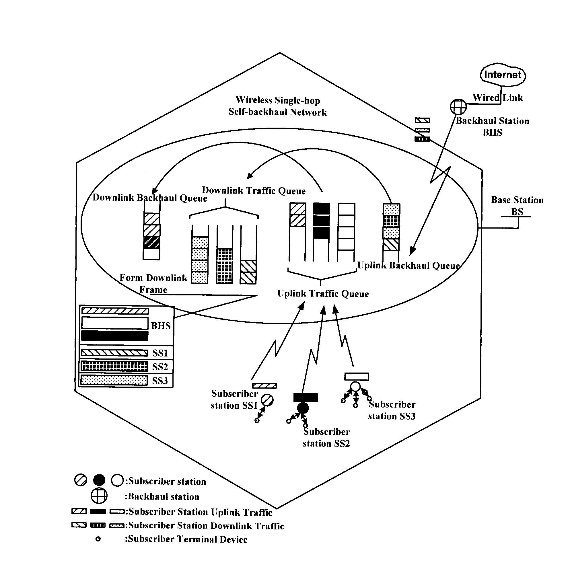
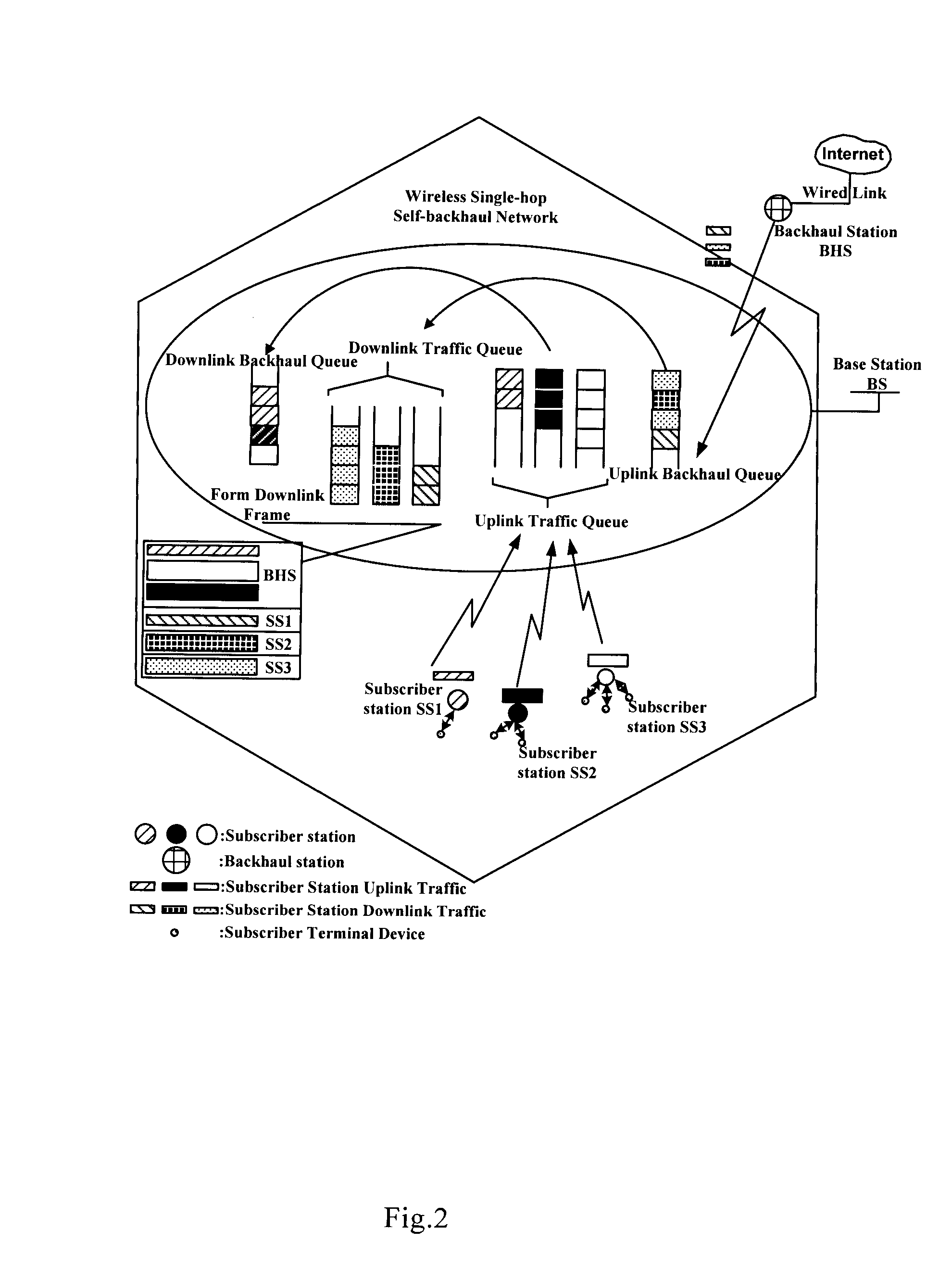
[0010] To this end, the present invention proposes a bandwidth allocation scheme in a wireless self-backhaul network (especially a wireless single-hop self-backhaul network), which allocates bandwidth for subscriber stations and backhaul station after taking into joint consideration uplink and downlink bandwidth requests from subscriber stations, so that a relatively high bandwidth utilization ratio and ideal fairness for uplink and downlink bandwidth can be ensured even if the wireless single-hop self-backhaul network is overloaded.

Problems solved by technology

However, the traditional allocation method, namely independent allocation of uplink and downlink bandwidth, does not apply to wireless single-hop self-backhaul networks.
This importantly difference makes the traditional bandwidth allocation method unsuitable for wireless single-hop self-backhaul networks.
Main problems are as follows: when the traditional bandwidth allocation method is applied to the network, if a sum of uplink and downlink traffic bandwidth exceeds a given threshold (i.e. network overload), the system bandwidth utilization ratio will decrease sharply with the increase in network overload; meanwhile, bandwidth fairness of uplink and downlink traffic for asymmetric service will be utterly destroyed.

Method used


Image

  • Method and base station for bandwidth allocation in wireless single-hop self-backhaul networks
  • Method and base station for bandwidth allocation in wireless single-hop self-backhaul networks
  • Method and base station for bandwidth allocation in wireless single-hop self-backhaul networks

Examples


Embodiment Construction

[0023] Referring to the accompanying drawings, a detailed description will be given to the present invention in terms of embodiments. It should be understood that the present invention is not limited to the embodiments.

[0024]FIG. 3 is a schematic view of a bandwidth request in the wireless single-hop self-backhaul network according to an embodiment of the present invention. In the present embodiment, the service configuration is as follows: in a cellular network there are two video conference services and forty VoIP speech services, and other subscriber services include four common services, namely FTTP, HTTP, database access and Email.

[0025]FIG. 4 is a flowchart of a method for bandwidth allocation in a base station of a wireless communication network according to an embodiment of the present invention, wherein said wireless communication network further comprises a plurality of subscriber stations and a backhaul station.

[0026] As shown in FIG. 4, uplink and downlink bandwidth a...


PUM


Abstract

The present invention discloses a method and a base station for allocating bandwidth for subscriber stations and a backhaul station through taking into joint consideration uplink and down bandwidth requests from respective subscriber stations in a wireless single-hop self-backhaul network. Upon receipt of information on bandwidth requests from the subscriber stations, the base station takes uplink and downlink bandwidth requests into joint consideration, allocates bandwidth for the subscriber stations and the backhaul station, and then notifies the subscriber stations and the backhaul station. Since bandwidth allocation is no longer based on uplink and downlink resources separately, a relatively high system bandwidth utilization ratio can be achieved and uplink and downlink bandwidth fairness for asymmetric traffic be ensured even if the network is overloaded.

Description

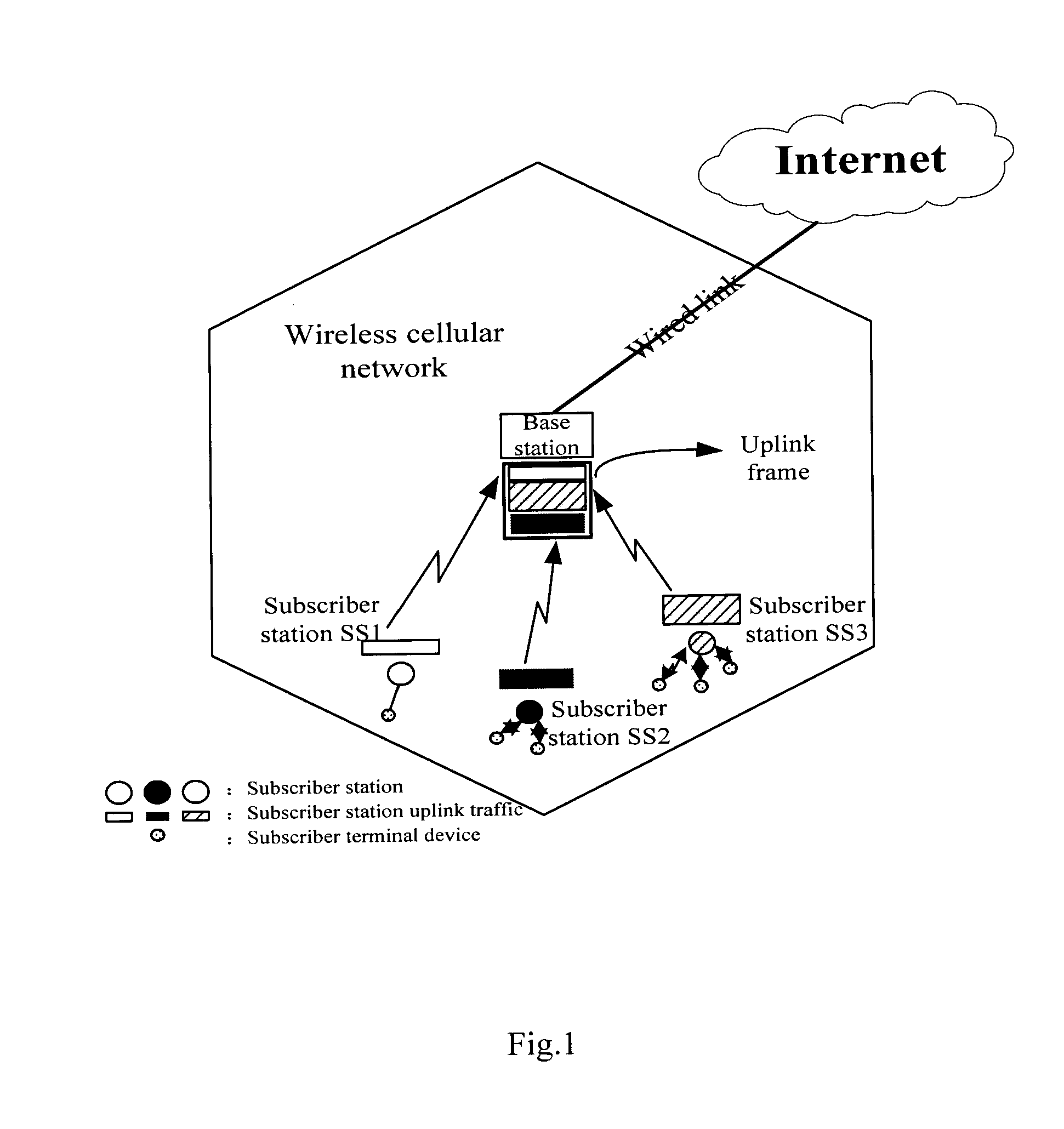
CROSS-REFERENCE TO RELATED APPLICATION(S) [0001] This application is based on the Chinese Patent Application No. 200510110322.2 filed on Nov. 11, 2005, the disclosure of which is hereby incorporated by reference. FIELD OF THE INVENTION [0002] The present invention relates to wireless communication networks, and particularly to a method and base station for bandwidth allocation in wireless self-backhaul networks (especially wireless single-hop self-backhaul networks). BACKGROUND OF THE INVENTION [0003] In a general point-to-multipoint (P2MP) wireless communications network, such as a cellular network (as shown in FIG. 1), subscriber stations (SS) access a base station by sharing wireless links, and the base station broadcasts information to every subscriber station through the wireless links. [0004] In the prior art, bandwidth allocation methods for general cellular networks are all based on the following supposition: bandwidth allocation for uplink traffic is independent of bandwidt...

Claims


Application Information

Patent Timeline
Patent Type & Authority Applications(United States)
IPC IPC(8): H04L12/56H04B7/216H04W28/20H04W72/14H04W92/12
CPCH04W72/0486H04W72/0453H04W92/12H04W72/52
Inventor LIU, ERWUQI, JIANGLENG, XIAOBINGLIU, JIMIN
Owner ALCATEL LUCENT SAS
Why Eureka
Try Eureka