Shutter driving apparatus for camera module

Inactive Publication Date: 2007-05-17
SAMSUNG ELECTRONICS CO LTD
View PDF8 Cites 30 Cited by
  • Summary
  • Abstract
  • Description
  • Claims
  • Application Information

AI Technical Summary

Benefits of technology

[0013] The present invention has been made to solve the above-mentioned problems occurring in the prior art, and the present invention, in one aspect, provides a shutter driving apparatus for a camera module, in which a pair of shutter driving sections are constructed to slidingly move shutter

Problems solved by technology

However, a drawback of the conventional shutter driving apparatus for the camera module, constructed as described above, is that, since the camera module 1 must define the space in which the shutter blade 5 can

Method used


Image

  • Shutter driving apparatus for camera module
  • Shutter driving apparatus for camera module
  • Shutter driving apparatus for camera module

Examples


Embodiment Construction

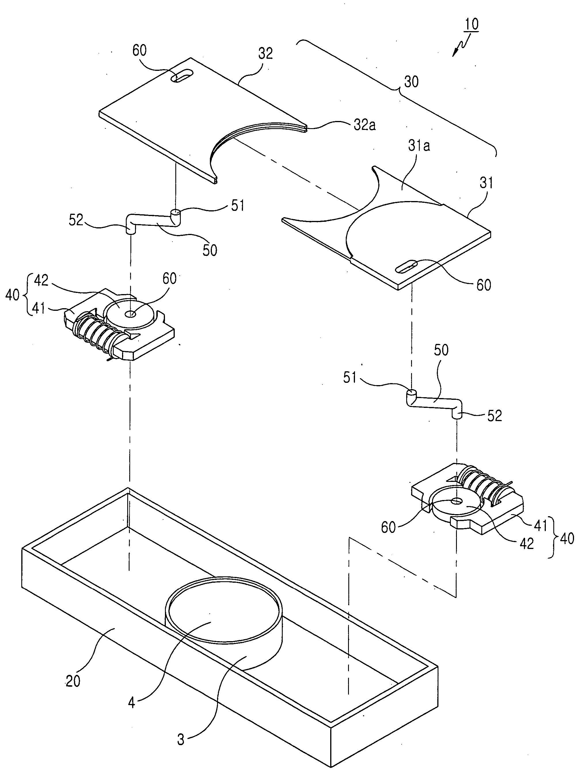
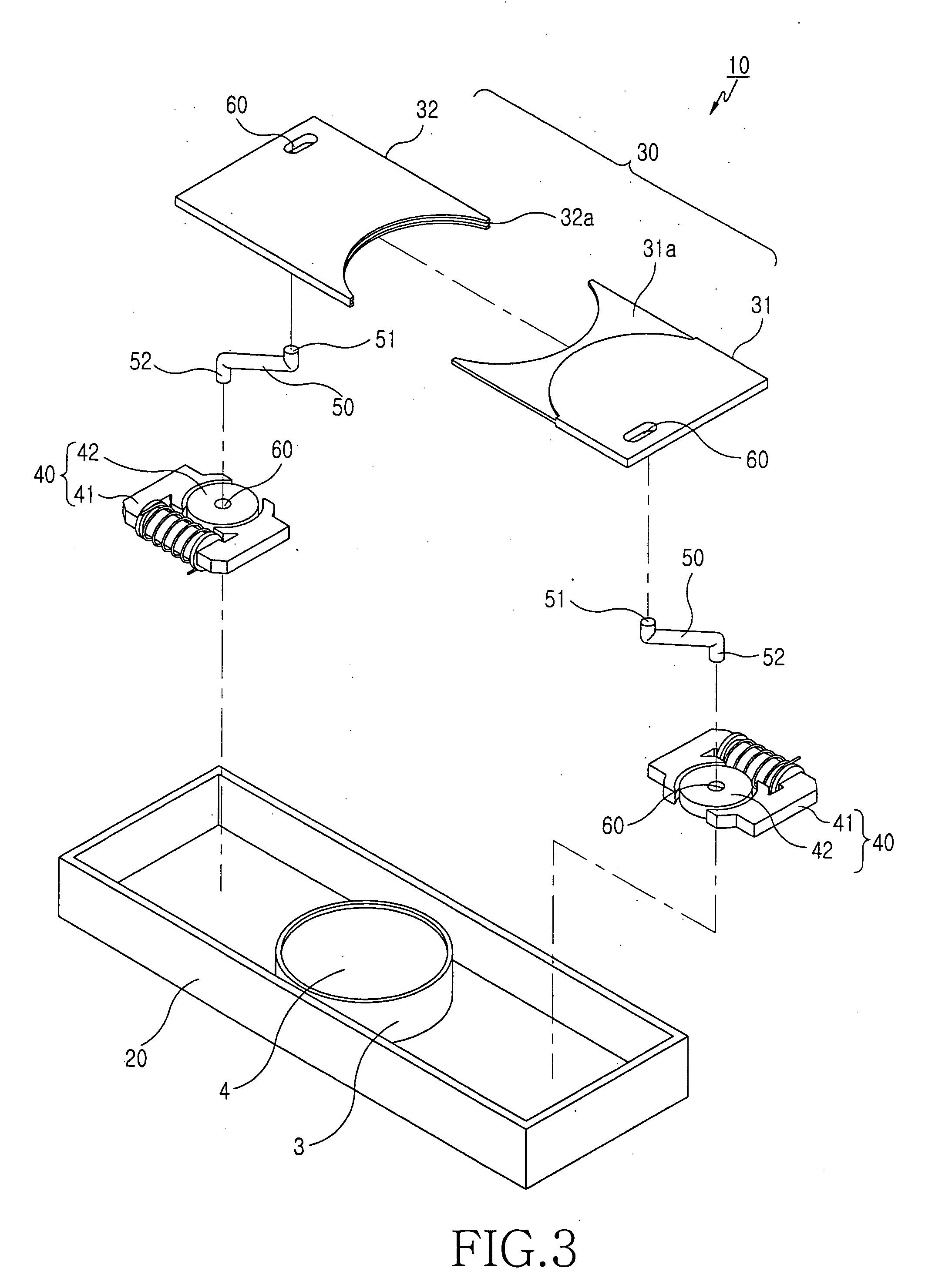
[0037] Referring to FIGS. 3 and 4, a shutter driving apparatus 10 for a camera module in accordance with a first embodiment of the present invention comprises a lens housing 20, a pair of shutter blades commonly represented by the reference numeral 30, and a pair of shutter driving sections 40. The lens housing 20 is configured to allow the shutter blades 30 to be slidingly moved therein. The shutter blades 30 are provided in the lens housing 20 so that they can be slidingly moved along the lengthwise direction of the lens housing to open and close a lens opening 4 of a lens module 3. The pair of shutter driving sections 40 are connected to the shutter blades 30 by respective rotation links 50 and are placed below the shutter blades 30. Each shutter driving section 40 has an electromagnet 41 and a permanent magnet 42 positioned between the poles of the electromagnet. The permanent magnet 42 is connected to the rotation link 50 and is rotated by a magnetic field, created as current i...


PUM


Abstract

A shutter driving apparatus for a camera module has a shutter driving section constructed to slidingly move shutter blades provided to a camera lens module in both sideward directions to thereby open and close a lens opening. The shutter driving apparatus comprises a lens housing; a pair of shutter blades provided to the lens housing to be slidingly moved in a lengthwise direction of the lens housing to thereby open and close a lens opening of the camera lens module; and a pair of shutter driving sections respectively connected to the shutter blades via rotation links and each being configured for creating a pair of electromagnetically-opposite electromagnet poles and having a permanent magnet positioned between the poles such that a permanent magnet with at least one of the poles and connected to the rotation link is rotated due to a magnetic field created as current is applied to the electromagnet, to slidingly move an associated shutter blade.

Description


Claims


Application Information

Patent Timeline
Owner SAMSUNG ELECTRONICS CO LTD
Why Eureka
Try Eureka