Air conditioning system

a technology of air conditioning system and air intake, which is applied in ventilation systems, heating types, separation processes, etc., can solve the problems of deteriorating heating efficiency, carbon dioxide increase, and difficult breathing of living things in closed spaces, and achieve high ventilation efficiency

Inactive Publication Date: 2007-05-24
LG ELECTRONICS INC
View PDF19 Cites 36 Cited by
  • Summary
  • Abstract
  • Description
  • Claims
  • Application Information

AI Technical Summary

Benefits of technology

[0011] An object of the present invention is to provide an air conditioning system that ventilates a plurality of indoor area compartments using a single ventilation unit and thus has a high ventilation efficiency when the total volume of the indoor area is considered.
[0012] Another object of the present invention is to provide an air conditioning system that can individually control the environments of many indoor area compartments.

Problems solved by technology

When a living thing breathes in a closed space, carbon dioxide increases with time, and thus it becomes more difficult for the living thing to breathe in the closed space.
However, only an air cleaning unit or ventilation device is provided in the related art ventilation system.
Therefore, for example, when the ventilation device operates in winter, heating efficiency is deteriorated since cold outdoor air is directly introduced into an indoor area.
Furthermore, since the ventilation device ventilates a number of indoor area compartments, ventilation efficiency of the device is low when the total size of the indoor area is considered.

Method used


Image

  • Air conditioning system
  • Air conditioning system
  • Air conditioning system

Examples


first embodiment

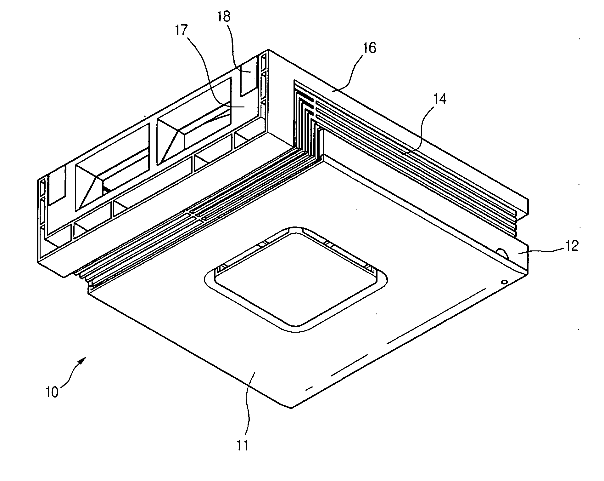
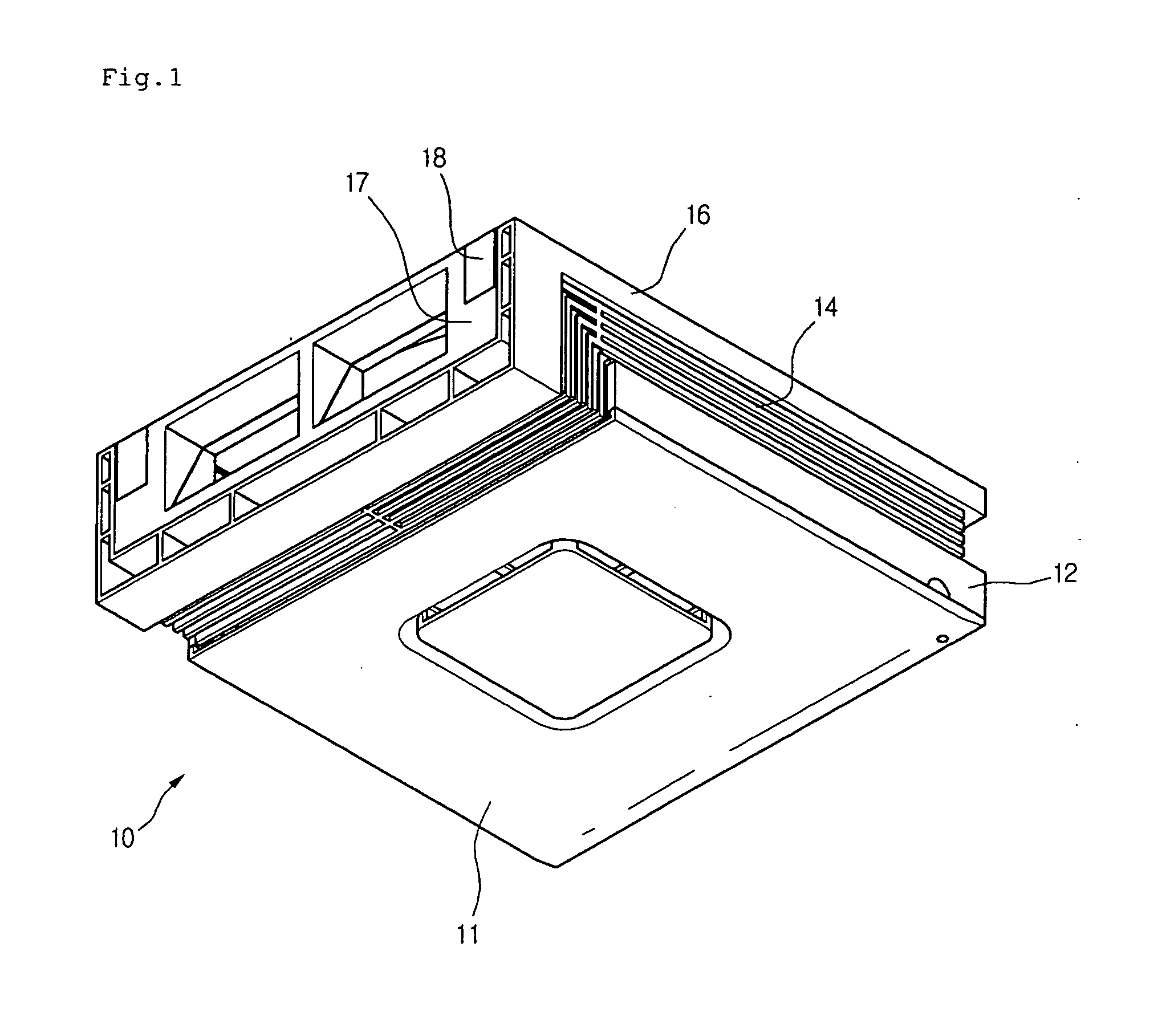
[0047]FIG. 4 is a perspective view showing an installation case according to the present invention.

[0048] Referring to FIG. 4, an installation case 17 of the current embodiment is characterized in that the installation case 17 is coupled to the air cleaning unit 10 when the air cleaning unit 10 is connected to a supply duct and an exhaust duct that are formed through a wall. When assemble, the installation case 17 is coupled to one side of the rear panel 16. In detail, one end of the rear panel 16 is bent downwardly (refer to FIG. 2). The bent end of the rear panel 16 is inwardly recessed in correspondence with the installation case 17 for receiving the installation case 17.

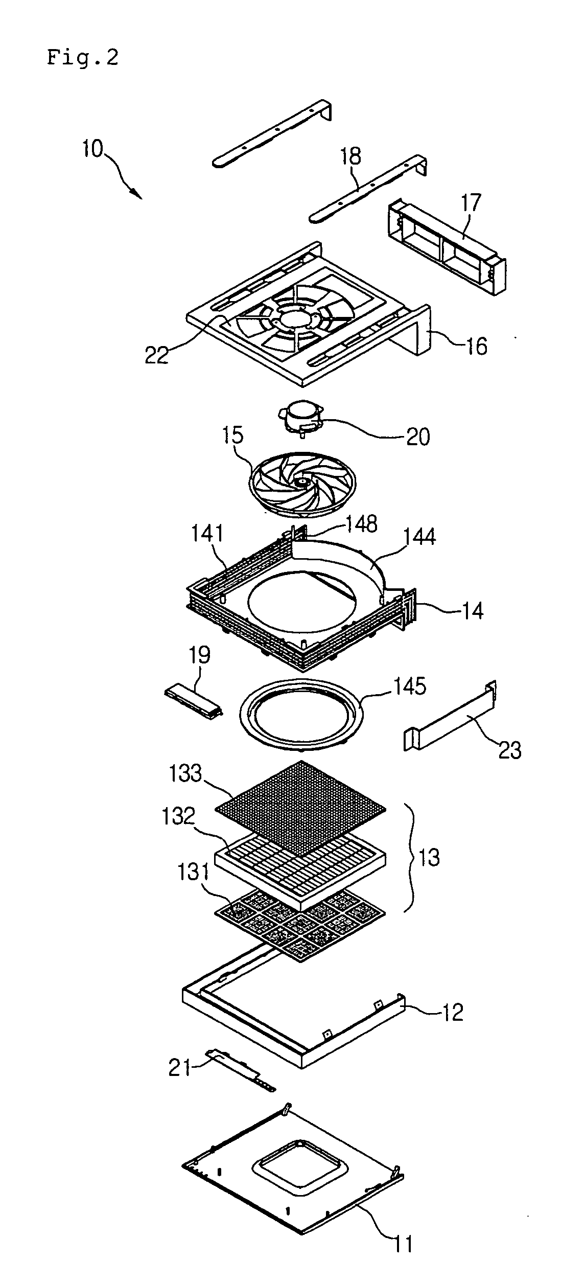
[0049] In detail, the installation case 17 includes bar receiving surfaces 171 on both top sides for receiving one ends of the installation bars 18, a wiring penetration hole 174 formed in an edge portion, and a suction hole 173 and an exhaust hole 172 formed through a front portion. The rear panel 16 includes a...

second embodiment

[0050]FIG. 5 is a perspective view showing the installation case of the air cleaning unit 10 according to the present invention.

[0051] Referring to FIG. 5, an installation case 27 of the current embodiment is characterized in that the installation case 27 is coupled to the air cleaning unit 10 when the air cleaning unit 10 is connected to a supply duct and an exhaust duct that are formed through a ceiling.

[0052] In detail, the installation case 27 includes a suction hole 273 and an exhaust hole 272 that are formed from a front surface to a top surface, bar receiving surfaces 271 formed in both top sides for receiving the installation bars 18, and bar inserting holes 271a formed in rear ends of the bar receiving surfaces 271 and having a predetermined width.

[0053] In more detail, the bent end of the installation bar 18 is inserted into the bar inserting hole 271a. The suction hole 273 and the exhaust hole 272 of the installation case 27 are connected to the suction hole and the exh...


PUM

PropertyMeasurementUnit
lengthaaaaaaaaaa
areasaaaaaaaaaa
humidityaaaaaaaaaa

Abstract

An air conditioning system is provided. The air conditioning system includes an air cleaning unit. The air cleaning unit includes a grill having a discharge grill on a side portion, a fan sucking indoor air and/or outdoor air, a filter cleaning the sucked air, and an installation case attached to one side of the discharge grill and having a suction hole and an exhaust hole. A ventilation unit operates in association with the air cleaning unit. A duct member connects the air cleaning unit and the ventilation unit.

Description

BACKGROUND OF THE INVENTION [0001] 1. Field of the Invention [0002] The present invention relates to an air conditioning system, and more particularly, to an air conditioning system in which an air cleaning unit operates in association with other air conditioning devices such a heat recovery ventilator. Further, the present invention relates to an air conditioning system in which a plurality of air cleaning units is connected to a single heat recovery ventilator. [0003] 2. Description of the Related Art [0004] When a living thing breathes in a closed space, carbon dioxide increases with time, and thus it becomes more difficult for the living thing to breathe in the closed space. Therefore, closed spaces, such as an office where a lot of people works together or the interior of a car, should be periodically ventilated. A ventilation system can be generally used for this purpose. [0005] Such a ventilation system is generally installed on a floor or a ceiling to allow inflow of outdoor...

Claims


Application Information

Patent Timeline
Patent Type & Authority Applications(United States)
IPC IPC(8): B01D46/00F24F1/035F24F8/108F24F7/003
CPCF24F3/1603F24F7/08F24F12/006Y02B30/563F24F2001/0096F24F2003/1614F24F2013/0616F24F2001/0037F24F1/0047F24F1/0071Y02B30/56F24F8/108F24F8/10F24F1/035F24F7/003Y02A50/20
Inventor SONG, CHANG HYUNLEE, HO BEOMPARK, JONG HOONKANG, DONG HOONBANG, KI SUK
Owner LG ELECTRONICS INC
Why Eureka
Try Eureka