Magnetoelectric generator

a generator and magnetoelectric technology, applied in the direction of magnetic circuit rotating parts, mechanical energy handling, shape/form/construction of magnetic circuits, etc., can solve the problems of increasing manufacturing costs, and achieve the effect of reducing manufacturing costs, high ventilation efficiency, and reducing manufacturing costs

Active Publication Date: 2005-10-27
MITSUBISHI ELECTRIC CORP
View PDF4 Cites 9 Cited by
  • Summary
  • Abstract
  • Description
  • Claims
  • Application Information

AI Technical Summary

Benefits of technology

[0006] It is an object of the present invention to solve the problem mentioned above by providing a magnetoelectric generator of an improved structure which ensures high ventilation efficiency internally of the flywheel while rendering unnecessary the work requiring a number of manufacturing steps and the dedicated resin forming metal mold, to thereby reduce the manufacturing cost.
[0007] In view of the above and other objects which will become apparent as the description proceeds, there is provided according to an aspect of the present invention a magnetoelectric generator which includes a flywheel of a substantially bowl-like shape having a bottom portion formed with ventilation holes, a plurality of permanent magnets fixedly secured to an inner circumferential surface of the flywheel, a stator core disposed internally of the flywheel and having peripheral side surfaces facing in opposition to the permanent magnets, and an electricity generating coil assembly implemented by winding an electric conductor on the stator core, wherein electricity is generated under the effect of electromagnetic induction produced between the permanent magnets and the electricity generating coil assembly by rotating the flywheel. A peripheral edge portion of the ventilation hole is formed with a projecting portion by plastic deformation, the projecting portion protruding toward the electricity generating coil assembly for producing turbulent flows of a fluid internally of the flywheel upon rotation of the flywheel.
[0008] With the magnetoelectric generator according to the present invention, the manufacturing cost can be reduced while assuring high ventilation efficiency within the inner space of the flywheel.

Problems solved by technology

However, because the fins are formed integrally with the flywheel by resorting to an insert mold forming process, there are required a number of steps for manufacturing the flywheel by using a dedicated resin forming metal mold, as a result of which the manufacturing cost increases, giving rise to a problem.

Method used


Image

  • Magnetoelectric generator
  • Magnetoelectric generator
  • Magnetoelectric generator

Examples


embodiment 1

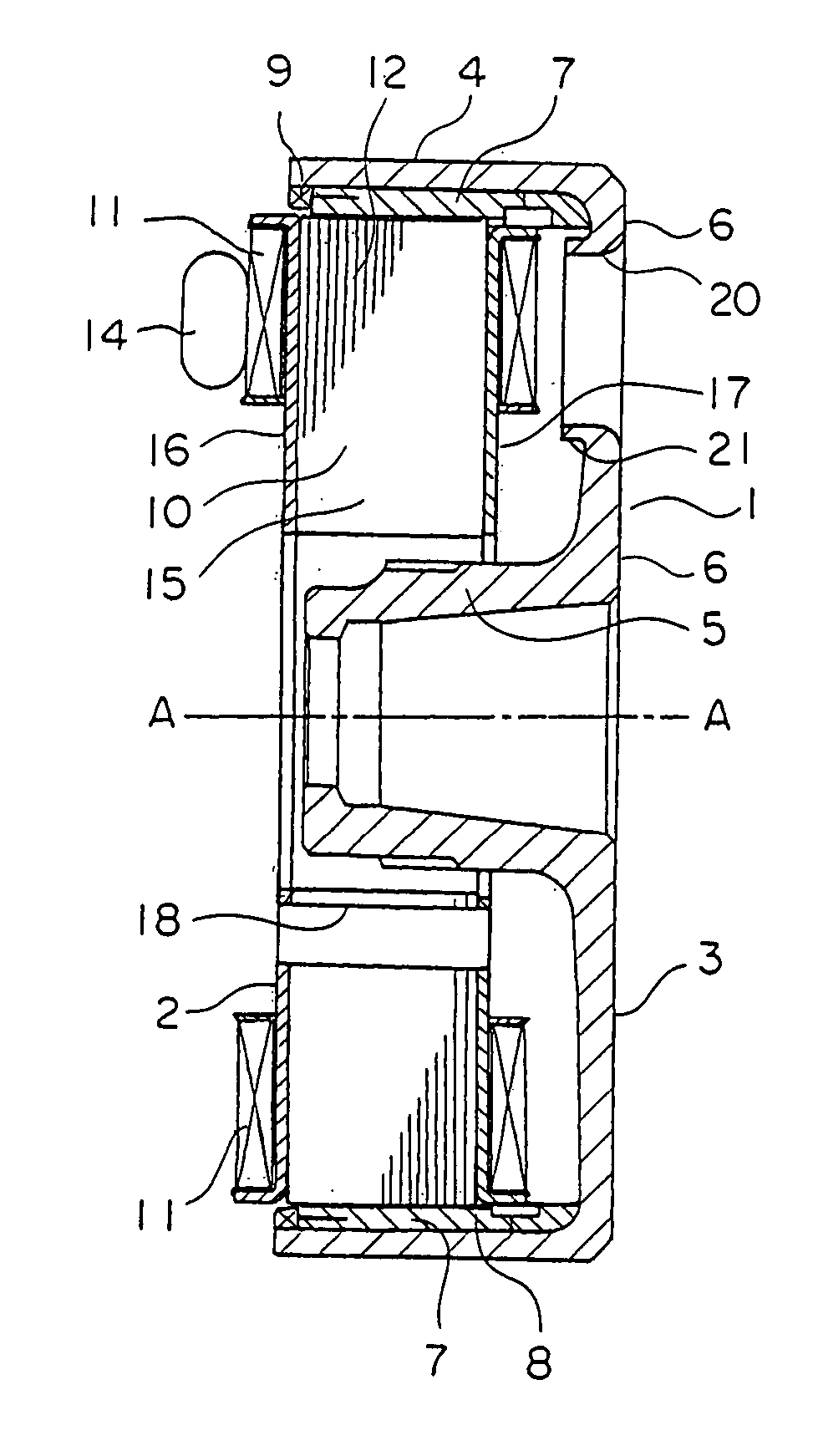
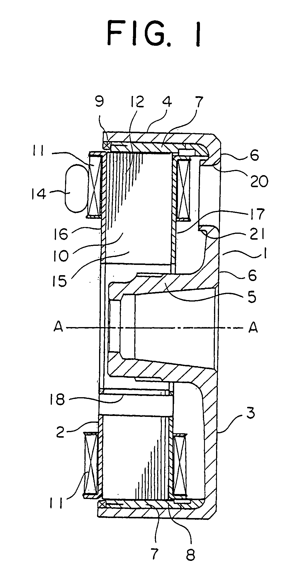
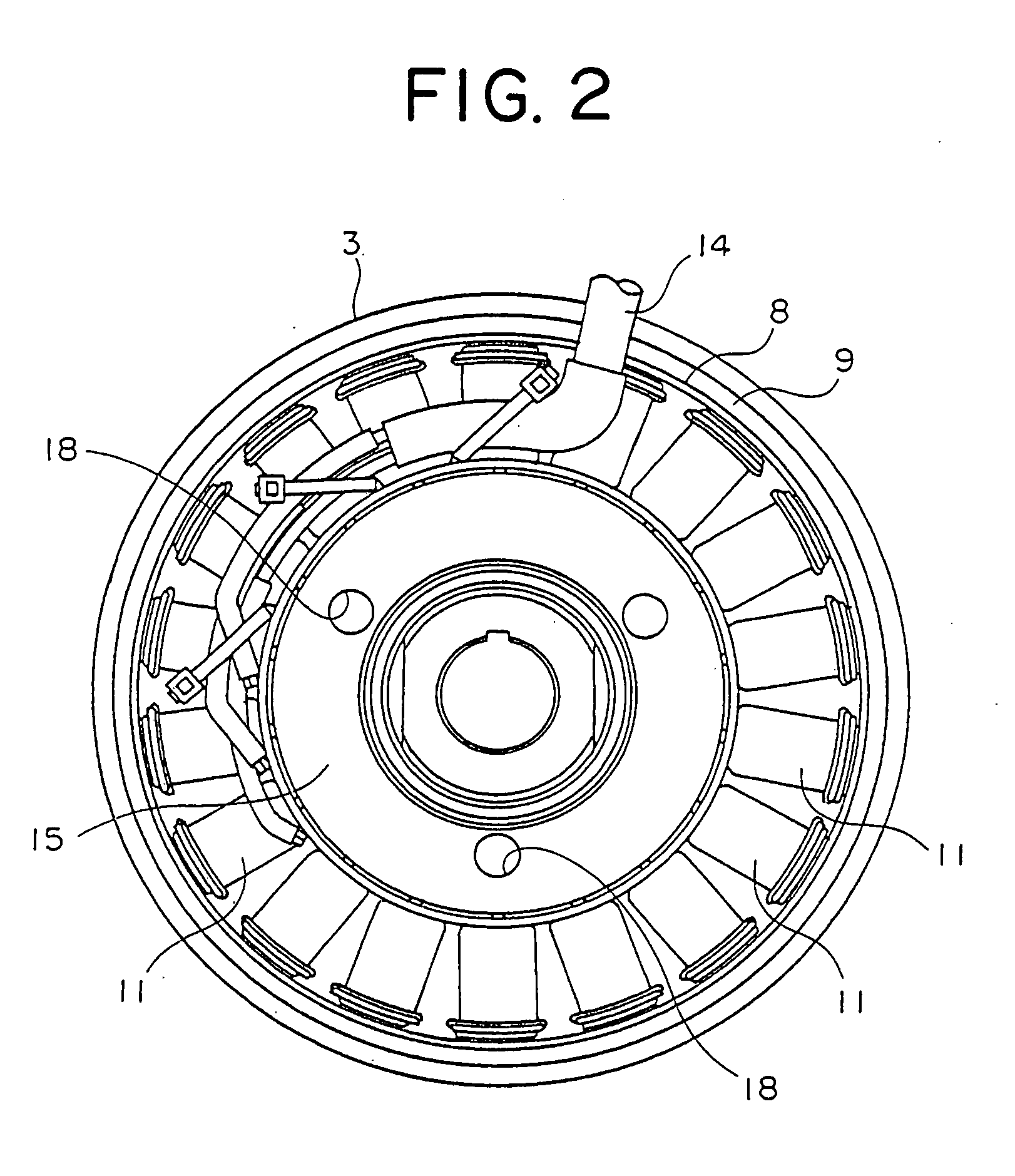
[0026]FIG. 1 is a vertical sectional view showing the magnetoelectric generator according to a first embodiment of the present invention and FIG. 2 is a side view of the same as viewed from the left-hand side in FIG. 1.

[0027] Referring to the figure, the magneto generator now under consideration includes a rotor 1 mechanically coupled to an internal combustion engine (not shown) and a stator 2 mounted on a stationary supporting member (not shown either) in opposition to the rotor 1.

[0028] The rotor 1 has a flywheel 3 of a substantially bowl-like shape which is composed of an outer peripheral cylindrical portion 4, a boss 5 formed at the inner side of the cylindrical portion 4 and a bottom portion 6 interconnecting the cylindrical portion 4 and the boss 5. The flywheel 3 is mounted rotatably about a rotation axis A-A. The boss 5 is fixedly secured to a rotatable shaft (not shown) driven by the internal combustion engine.

[0029] A plurality of permanent magnets 7 are fixedly mounted...

embodiment 2

[0046]FIG. 6 is a sectional view showing a major portion of the flywheel 3 of the magnetoelectric generator according to a second embodiment of the present invention. In the case of the magnetoelectric generator now concerned, a projection member 22 of a cylindrical shape having a collar 22a is press-fitted into each of the ventilation holes 20. The projection member 22 is made of an aluminum material which is a non-magnetic material exhibiting a high heat radiation property.

[0047] With the structure of the magnetoelectric generator according to the second embodiment of the invention, ventilation within the flywheel 3 can be promoted by press-fitting the projection member 22 into each of the ventilation holes 20, whereby electricity generation of high efficiency can be ensured similarly to the case of the magnetoelectric generator according to the first embodiment of the invention.

[0048] Further, since the collar 22a of the projection member 22 press-fitted into the ventilation ho...

embodiment 3

[0050]FIG. 7 is a sectional view showing a major portion of the flywheel 3 of the magnetoelectric generator according to a third embodiment of the present invention. In the case of the magnetoelectric generator now concerned, a projection member 23 is fixedly secured to each of the ventilation holes 20. This projection member 23 is formed of a plate- or sheet-like member having a plurality of notched portions 24a and 24b formed equi-distantly (see FIG. 8) and bent or rolled into a cylindrical or sleeve-like form. After having inserted the projection member 23 of the cylindrical form into the ventilation hole 20, the notched portions 24a and 24b are bent so that the projection member 23 can be secured fixedly to the ventilation hole 20.

[0051] With the structure of the magnetoelectric generator according to the third embodiment of the invention, by securing the projection member 23 to the ventilation hole 20, ventilation within the flywheel 3 can be promoted, whereby high electricity...


PUM


Abstract

A magnetoelectric generator includes a bowl-like flywheel (3) having a bottom portion (6) formed with ventilation holes (20), a plurality of permanent magnets (7) secured to an inner circumferential surface of the flywheel (3), a stator core (10) disposed within the flywheel (3) and having peripheral side surfaces facing the permanent magnets (7), and a coil assembly (11) implemented by winding an electric conductor on the core (10). Electricity is induced in the coil assembly (11) by AC magnetic field produced by rotating the flywheel (3). A peripheral edge portion of each ventilation hole (20) is formed with a projecting portion (21) by plastic deformation, which protrudes toward the coil assembly (11) for producing turbulent air flows internally of the flywheel (3) upon rotation of the flywheel (3).

Description

BACKGROUND OF THE INVENTION [0001] 1. Field of the Invention [0002] The present invention relates to a magnetoelectric generator (also known as magneto generator or simply as magneto) for generating electric energy under the effect of an electromagnetic induction produced between permanent magnets and an electricity generating coil assembly by rotating a flywheel. [0003] 2. Description of Related Art [0004] As the conventional magnetoelectric generator known heretofore, there has been proposed such one in which ventilation holes are formed in a bottom portion of a flywheel of a substantially bowl-like shape, wherein fins projecting into an inner space defined by the flywheel are formed between the adjacent ones of the ventilation holes. For more particulars, reference may have to be made to, for example, Japanese Patent Application Laid-Open No. 101630 / 2002 (JP-A-2002-101630). [0005] In the conventional magnetoelectric generator, ventilation efficiency can certainly be enhanced inte...

Claims


Application Information

Patent Timeline
Patent Type & Authority Applications(United States)
IPC IPC(8): H02K9/02H02K1/27H02K1/32H02K7/00H02K9/00H02K9/06H02K21/14H02K21/22
CPCH02K1/2786H02K9/06H02K1/32H02K1/2791
Inventor UEMURA, FUMITOHASHIBA, MITSUHARUKIHARA, NOBUHIRO
Owner MITSUBISHI ELECTRIC CORP
Why Eureka
Try Eureka