
Steering lock device

a technology of locking device and locking mechanism, which is applied in the direction of mechanical control device, anti-theft device, instruments, etc., can solve the problems of difficult intervention by thieves from the outside, and achieve the effect of increasing the effort required to steal, being inexpensive to produce and assembl

Inactive Publication Date: 2007-05-24
KHOURY JOSEPH E +3
View PDF34 Cites 19 Cited by
  • Summary
  • Abstract
  • Description
  • Claims
  • Application Information

AI Technical Summary

Benefits of technology

[0008] An object of the invention is to provide a device which decreases the probability that a thief will be able to steer the wheel of a hot-wired automobile. Another object of the invention is to provide a steering lock device that separates the ignition function from the anti-rotation function.
[0009] Disclosed are four independent design features that decrease the probability that a thief will be able to steer the wheel of a hot-wired automobile. The first feature of the invention includes a steering lock device that separates the ignition function from the anti-rotation function.
[0014] Thus, the invention achieves the objectives set forth above. The invention provides a device which is physically separate from the ignition function and which increases the effort required to steal an automobile equipped with the steering lock device. Additionally, the device fits within existing real estate on the steering column and has few moving parts which are inexpensive to produce and assemble. Therefore, even in the most violent of environments, the steering lock device will perform as intended and deter the theft of the vehicle.

Problems solved by technology

This feature makes any thief intervention from the outside very difficult.

Method used


Image

  • Steering lock device
  • Steering lock device
  • Steering lock device

Examples


Embodiment Construction

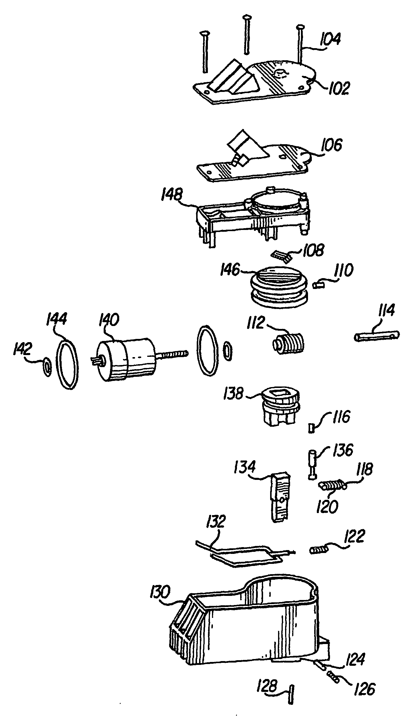
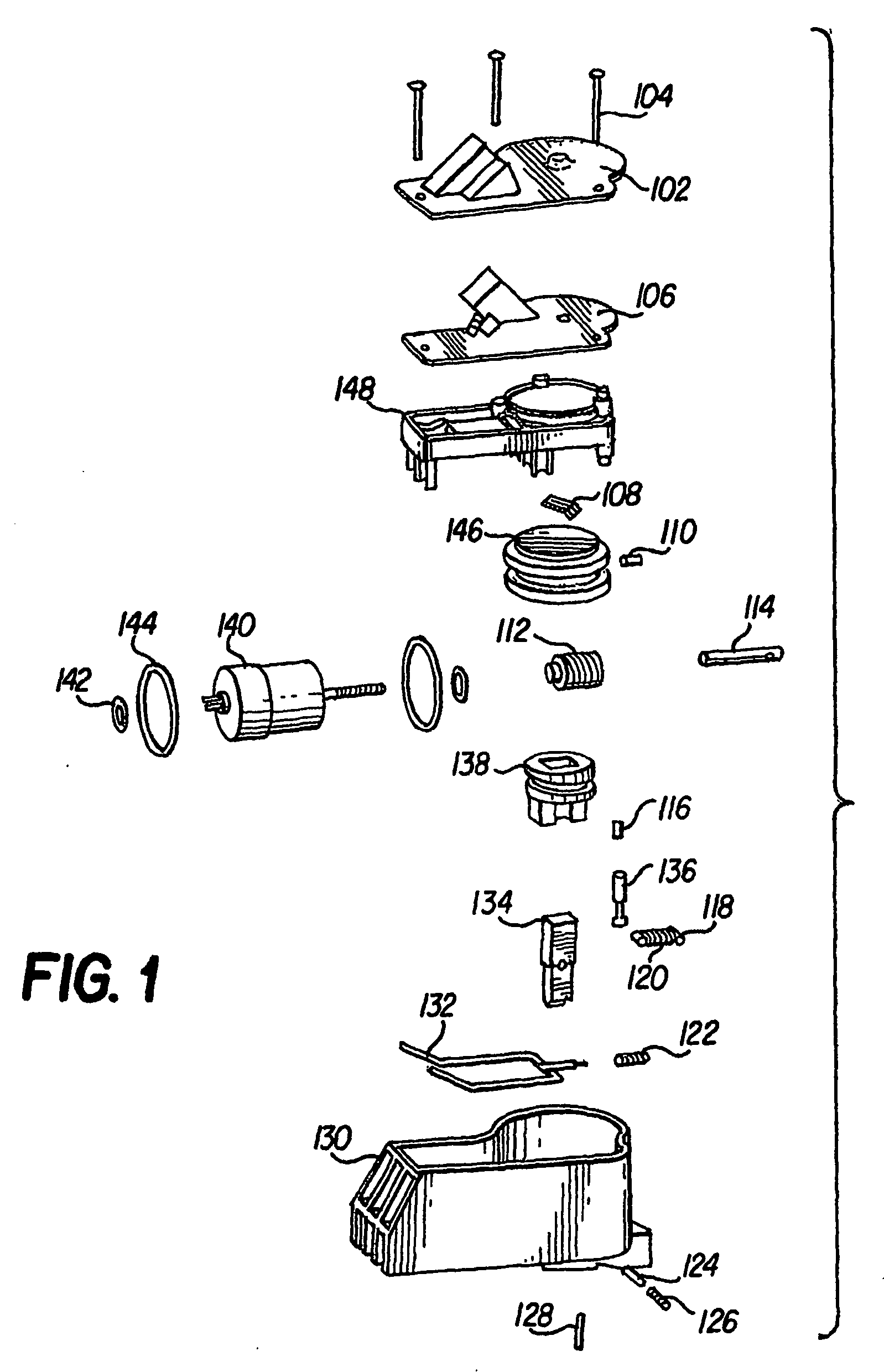
[0026] The present invention includes a locking device for locking a steering shaft to a steering column to prevent rotation of the steering shaft during a period of time. The locking device may be used as a safety and anti-theft device for automobiles.

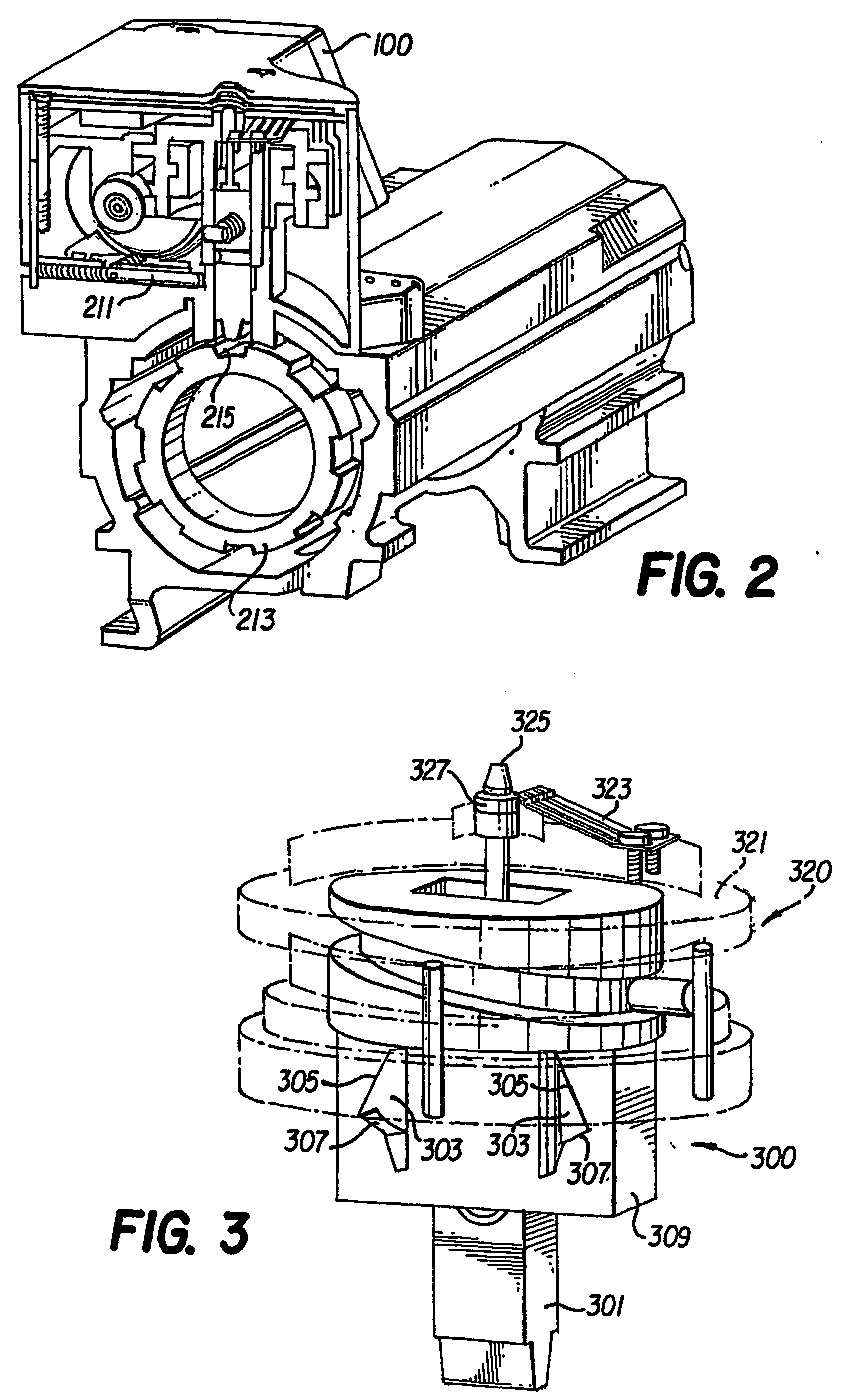
[0027] The present invention provides a steering lock device that separates the ignition function from the anti-rotation function. A clutch mechanism and a lock bolt drive system provide a lock bolt that can be engaged / disengaged with the steering shaft when the ignition key is turned to start or stop the automobile. A metal case covering the lock mechanism makes any thief intervention from outside very difficult.

[0028] The system of the present invention locks the locking bolt if the metal case is broken or any key mechanical component inside becomes loose.

[0029] Referring now to the drawings, wherein like reference numerals designate identical or corresponding parts throughout the several views, and more particularly to FIGS. 1-2...


PUM


Abstract

A lock bolt is engages with a recess formed on the surface of the steering shaft. In a locked position, the lock bolt engages the recess of the steering shaft. In an unlocked position, the lock bolt is withdrawn and disengaged from the recess. When the ignition key is turned to start the automobile, the lock bolt disengages the steering shaft. When the ignition key is turned to stop the automobile engine from idling, the lock bolt engages the steering shaft.

Description

BACKGROUND OF THE INVENTION [0001] 1. Field of the Invention [0002] The present invention relates to locking devices used in automotive applications. The invention more particularly concerns the locking of a steering shaft to a steering column of an automobile so as to prevent rotation of the steering shaft during selected periods of time. Thus, the locking device can be used as a safety device and an anti-theft device. [0003] 2. Description of the Prior Art [0004] For years now, automobile manufacturers have been including, as a standard feature, the feature of an immobilized steering shaft when the ignition key is not inserted into the ignition switch. The immobilized steering shaft prevents the steering wheel from rotating, thus, someone not having the ignition key can not steer the car if the car is hot-wired or if someone attempts to push the car away. The theft deterrent function works so well that people who attempt to take a car without using a key, typically, employ a large...

Claims


Application Information

Patent Timeline
Patent Type & Authority Applications(United States)
IPC IPC(8): B60R25/02
CPCB60R25/02153Y10T70/5664
Inventor KHOURY, JOSEPH E.RUEGENBERG, ROLANDKARASIK, VLADIMIRSHAHAN, MIKE
Owner KHOURY JOSEPH E
Learn More