

Leak inspection device
- Summary
- Abstract
- Description
- Claims
- Application Information
AI Technical Summary
Benefits of technology
Problems solved by technology
Method used
Image

Examples
Embodiment Construction
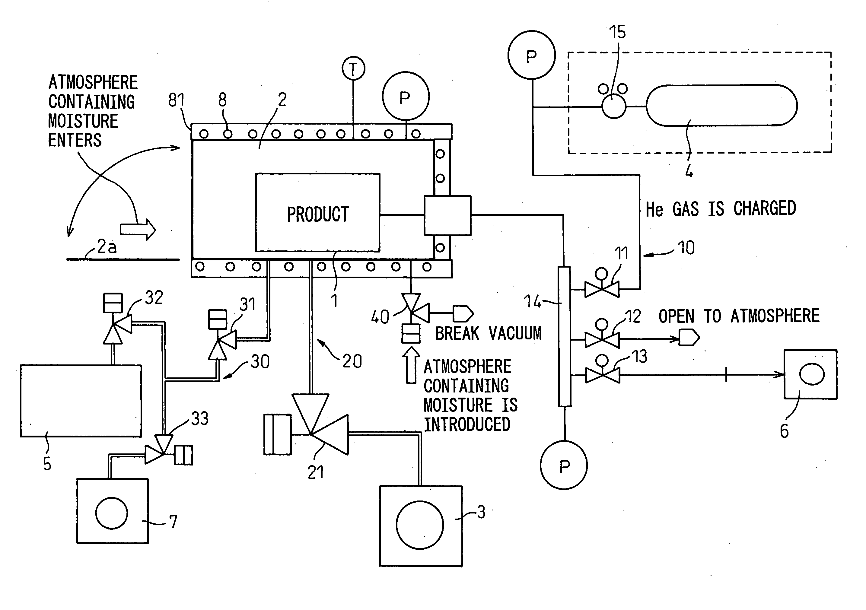
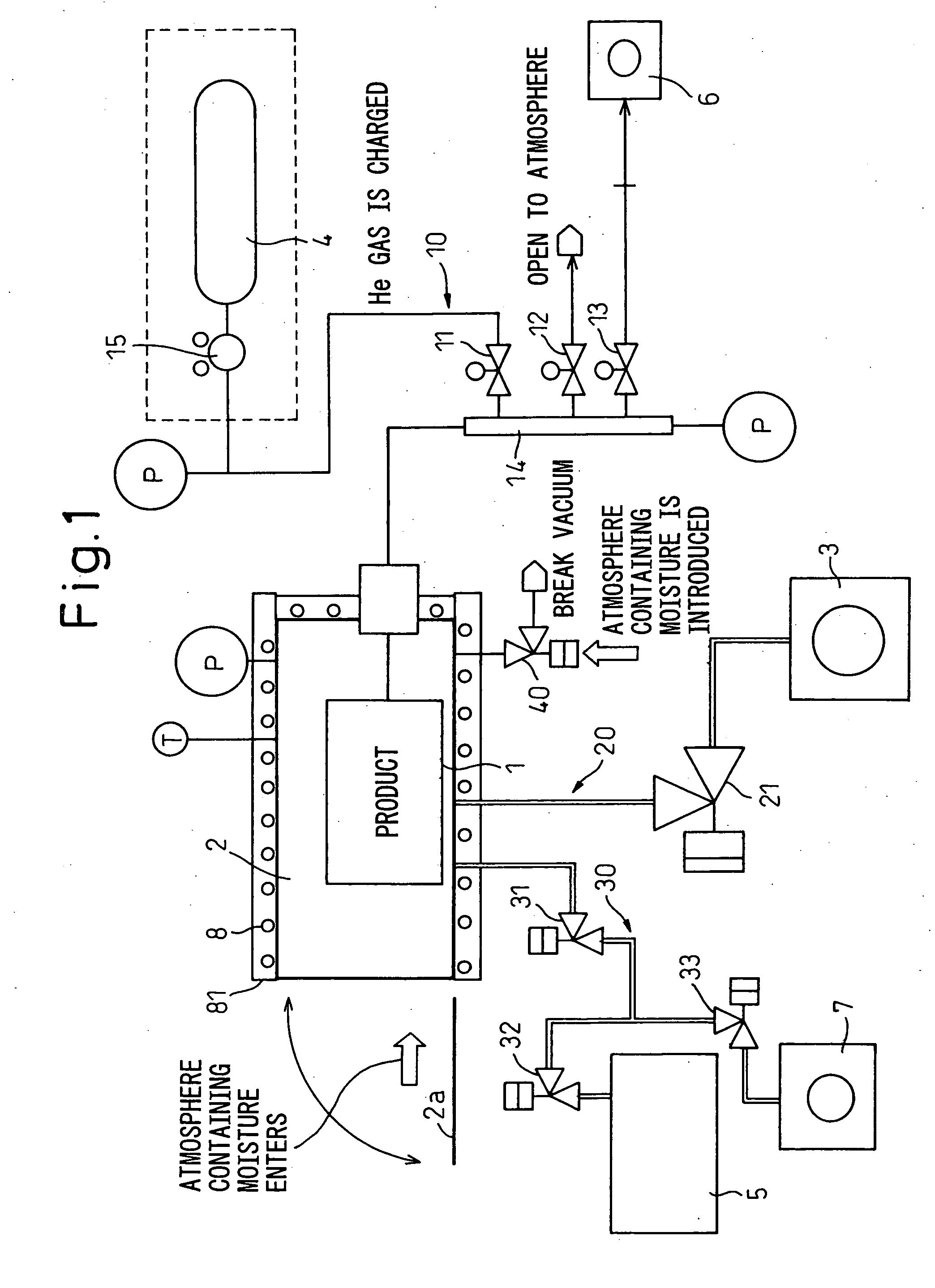
[0020] Referring to the drawings, a leak inspection device of an embodiment of the present invention will be explained below. FIG. 1 is an overall arrangement view showing an outline of the leak inspection device of the embodiment of the present invention. The leak inspection device basically includes: a vacuum chamber 2 for accommodating a product 1 which is an object to be inspected; a vacuum pump 3 for discharging air from the vacuum chamber 2; a helium bomb (gas cylinder) (He bomb) 4, which is a tracer gas supply source, for supplying a tracer gas such as helium gas (He gas) into the product 1; and a leak detector 5 for detecting He gas which has leaked out from the product 1.
[0021] The vacuum chamber 2 has a capacity in which the product 1, the size of which is variously changed, can be accommodated. On one side of the vacuum chamber 2, an opening and closing door 2a for taking in and out the product 1 is provided. On the outer walls of the vacuum chamber 2, a heater 8, which ...
PUM
 Abstract
Description
Claims
Application Information