

Apparatus for driving plasma display panel and plasma display
a technology for driving apparatuses and plasma displays, which is applied in the direction of instruments, static indicating devices, etc., can solve the problems of difficult to save power consumption and curtail the number of parts at the same time, so as to reduce the size of the driving apparatus, reduce the mounting area, and reduce the wiring impedance
- Summary
- Abstract
- Description
- Claims
- Application Information
AI Technical Summary
Benefits of technology
Problems solved by technology
Method used
Image

Examples
embodiment 1
1.1 Configuration
1.1.1 Plasma Display
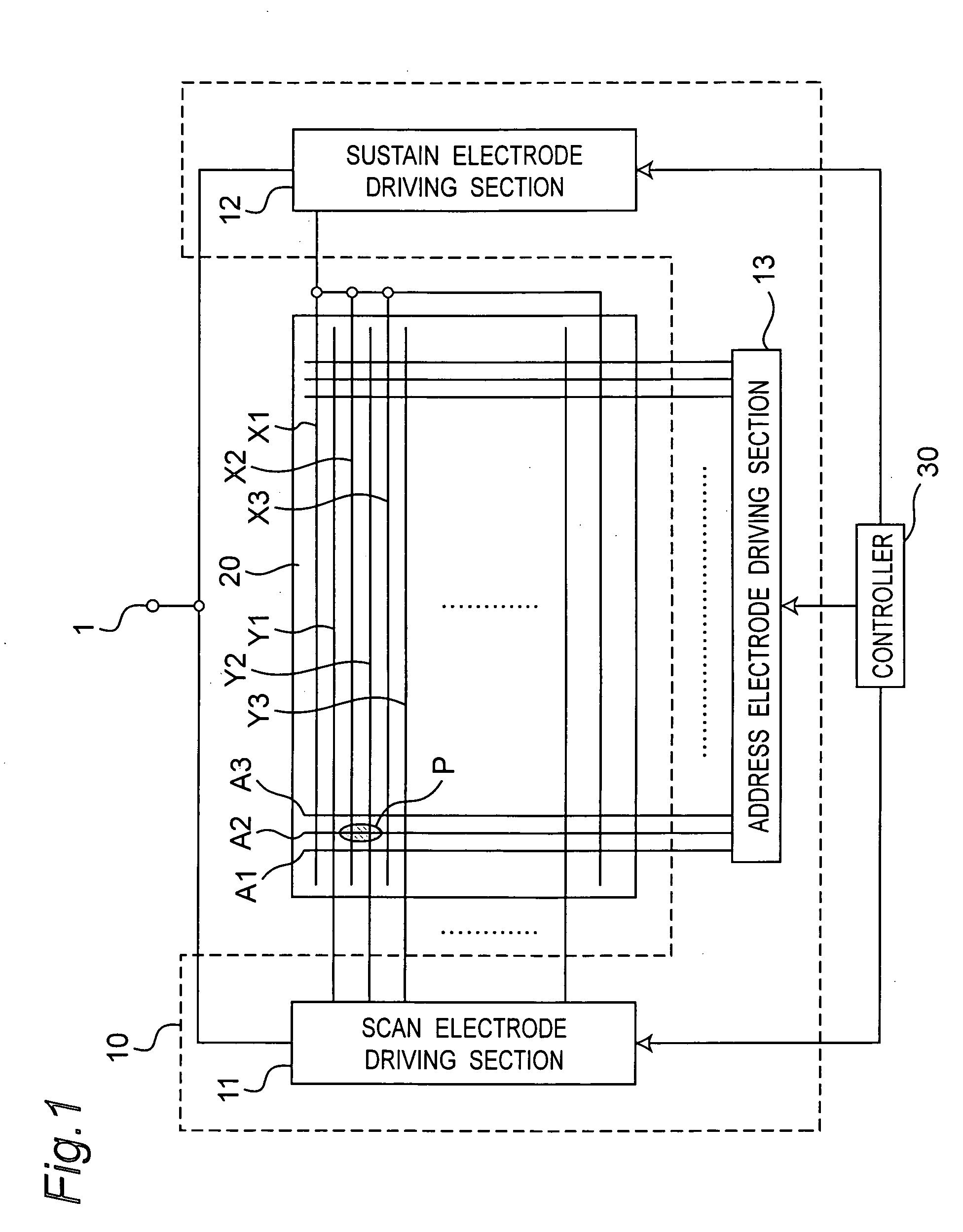
[0037]FIG. 1 is a block diagram showing a configuration of a plasma display in an embodiment of the invention. The plasma display includes a PDP driving apparatus 10, a plasma display panel (PDP) 20, and a controller 30.
(Plasma Display Panel)
[0038] The PDP 20 is, for example, of AC type, having three-electrode surface discharge type structure. On a back surface of the PDP 20, address electrodes A1, A2, A3, . . . are disposed along the width direction of the panel. On a front surface of the PDP 20, sustain electrodes X1, X2, X3, . . . and scan electrodes Y1, Y2, Y3, . . . are disposed alternately along the longitudinal direction of the panel. The sustain electrodes X1, X2, X3, . . . are mutually coupled to be substantially equal in the potential. The address electrodes A1, A2, A3, . . . , and scan electrodes Y1, Y2, Y3, . . . can be controlled individually for the potential.
[0039] A discharge cell is disposed at an intersection (for exampl...
embodiment 2
[0093] The plasma display of this embodiment differs from embodiment 1 only in the structure of scan electrode driving section 11.
2.1 Scan Electrode Driving Section
[0094]FIG. 4 shows the scan electrode driving section in embodiment 2 of the invention.
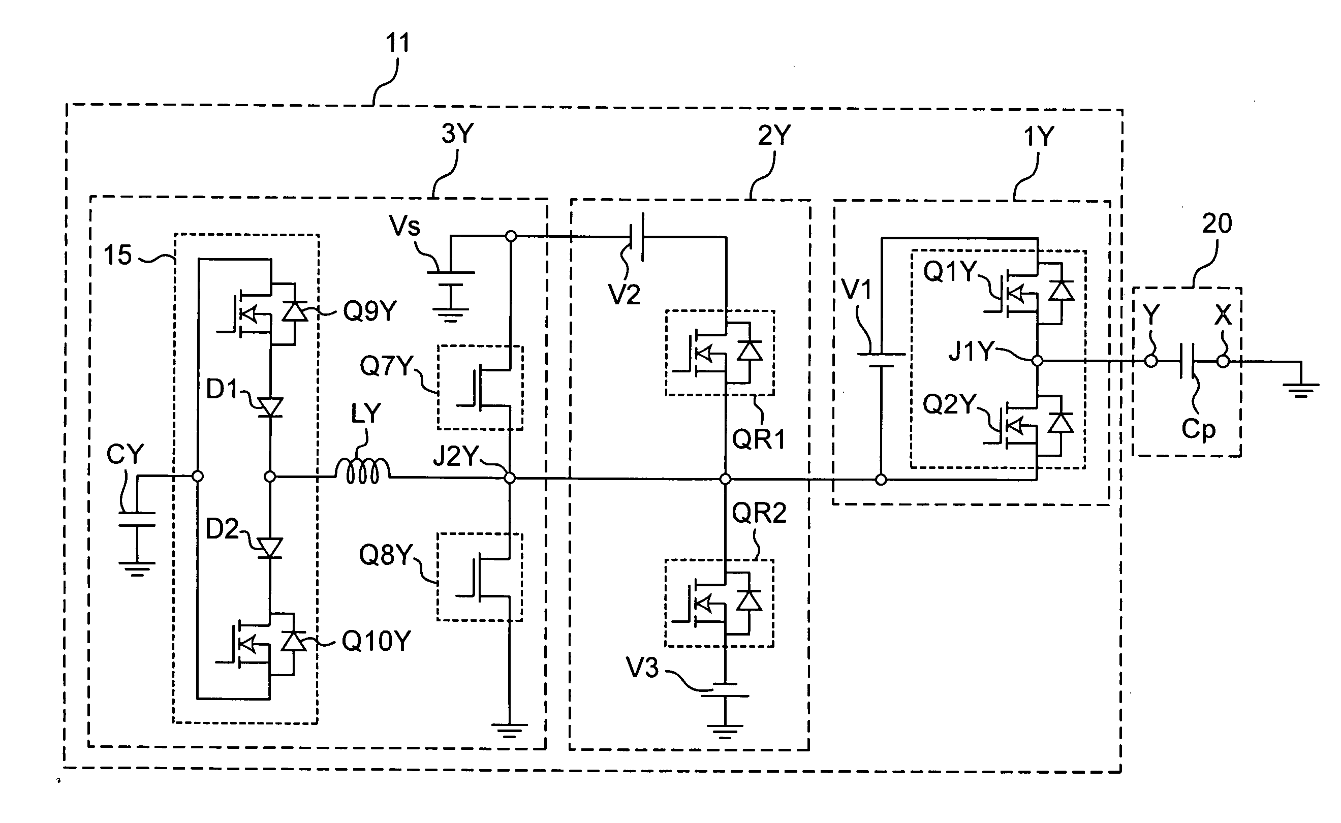
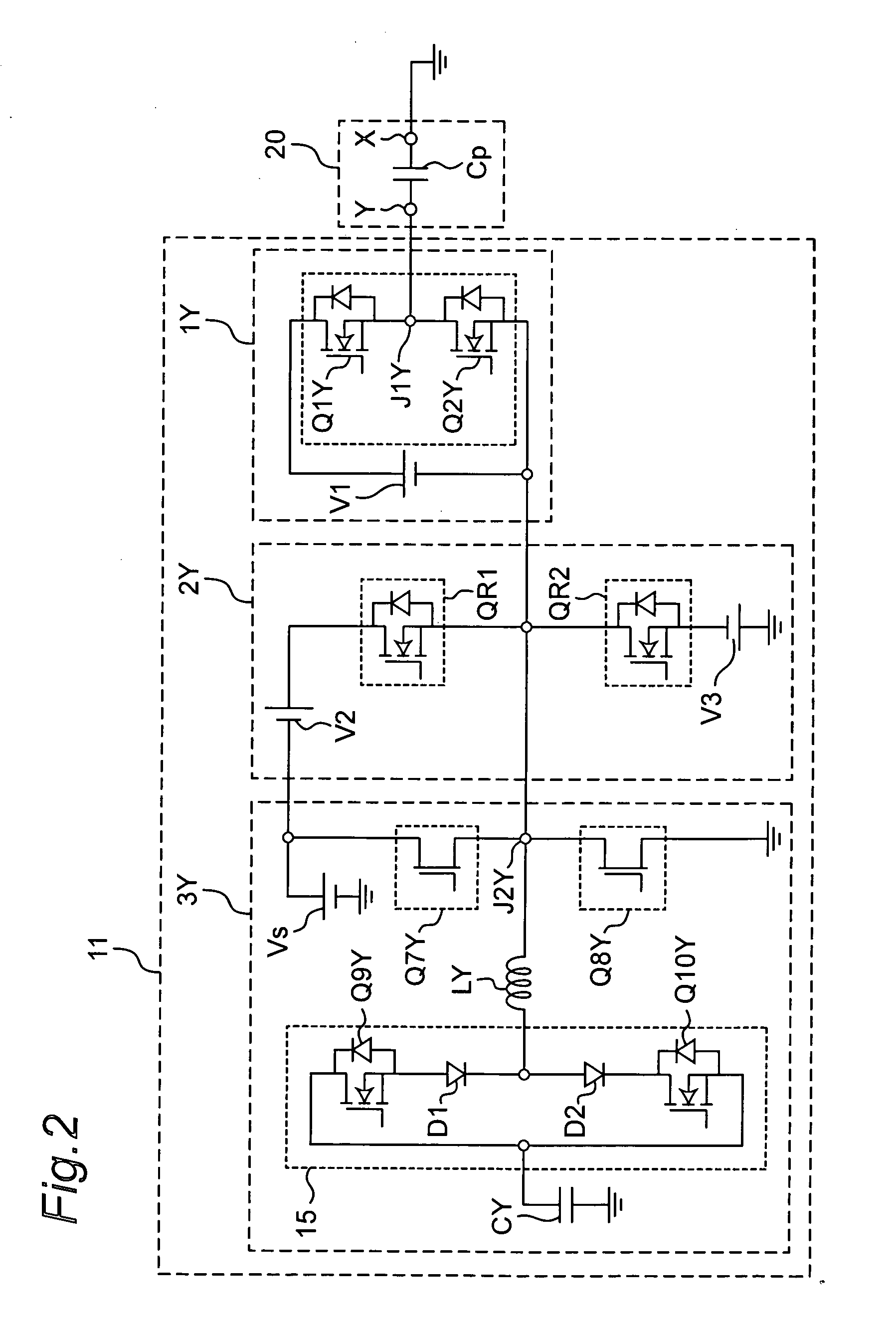
[0095] The scan electrode driving section 11 of the embodiment differs from embodiment 1 shown in FIG. 2 in the structure of the sustain pulse generating section. More specifically, the recovery switch circuit in the sustain pulse generating section is different. The other components are same as those in embodiment 1.
[0096] The sustain pulse generating section 4Y of the present embodiment is provided with a recovery switch element Q11Y instead of the recovery switch circuit 15 in the sustain pulse generating section 3Y in embodiment 1. This recovery switch element Q11Y is formed of a bidirectional switch element. The bidirectional switch element is explained in embodiment 1.
[0097] Thus, replacement of the recovery switch circuit 1...
embodiment 3
[0113] The plasma display of this embodiment differs from embodiment 1 only in the structure of the scan electrode driving section 11.
3.1 Scan Electrode Driving Section
[0114]FIG. 6 shows the scan electrode driving section 11 in embodiment 3 of the invention.
[0115] The scan electrode driving section 11 of the present embodiment differs from embodiment 1 shown in FIG. 2 in the structure of the reset pulse generating section and sustain pulse generating section. The other components are same as in embodiment 1.
[0116] The reset pulse generating section 5Y of the present embodiment has a separation switch element QS3, in addition to the structure of the reset pulse generating section 5Y of embodiment 1. This separation switch element QS3 is formed of a bidirectional switch element. The separation switch element QS3 has its source connected to the negative electrode of the second constant voltage source V2, and its drain connected to the negative electrode of the first constant volta...
PUM
 Abstract
Description
Claims
Application Information