
Ball bearing

Inactive Publication Date: 2007-05-24
NTN CORP
View PDF6 Cites 24 Cited by
  • Summary
  • Abstract
  • Description
  • Claims
  • Application Information

AI Technical Summary

Benefits of technology

[0009] More specifically, the ball bearing according to the present invention comprises the retainer having the pockets which are elliptical or elliptical with a discontinuous portion to receive the balls, and the spaces are provided between the pockets and the balls in the rotational direction of the bearing, the spaces being designed to account for 4-10%, preferably 6-10%, of the diameter of the balls, so as to reduce collisions between the retainer and the balls even though the balls rotate alternately faster and slower than the retainer at short intervals, without reducing the stiffness of the bridges of the retainer or the connecting spaces at the connecting portions.
[0015] The ball bearing according to the present invention comprises the retainer having the pockets which are elliptical or elliptical with a discontinuous portion to receive the balls, and the spaces are provided between the pockets and the balls in the rotational direction of the bearing, the spaces being 4-10%, preferably 6-10%, of the diameter of the balls. With this arrangement, it is possible to reduce collisions between the balls and the retainer, without reducing the stiffness of the bridges of the retainer or the connecting spaces at the connecting portions.

Problems solved by technology

The spaces in the rotational direction defined between the pockets and the balls are determined not to exceed 10% of the diameter of the balls, because otherwise the sectional area of the bridges and thus their stiffness decrease if the retainer has such bridges between the pockets, and if the retainer comprises a pair of annular members having hemispherical pockets and connecting portions provided between the adjacent pockets, and connected together at the connecting portions, the connecting spaces at the connecting portions tend to be insufficient.

Method used


Image

  • Ball bearing
  • Ball bearing
  • Ball bearing

Examples


Embodiment Construction

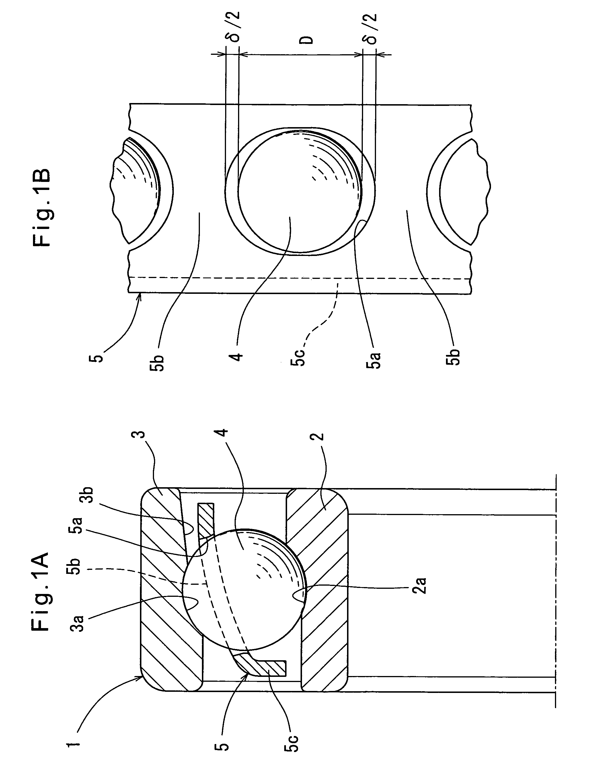
[0025] Now referring to the drawings, FIGS. 1A and 1B show a ball bearing according to the first embodiment of this invention. It is an angular ball bearing 1 comprising an inner ring 2 having a raceway groove 2a, an inner ring 3 having a raceway groove 3a, a plurality of balls 4 disposed between the raceway grooves 2a and 3a, and a retainer 5 retaining the balls 4. A countersink 3b is formed in the outer ring 3 on one side of the raceway groove 3a.

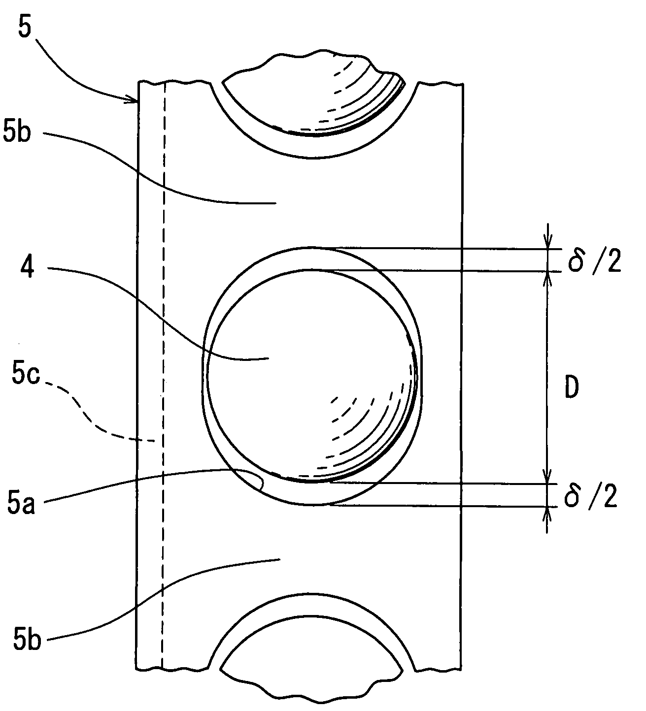
[0026] The retainer 5 is an annular member formed by pressing a metal sheet and has pockets 5a formed by punching. The balls 4 are each received in one of the pockets 5a. The retainer 5 includes annular portions formed on both sides of the pockets 5a and connected to each other by bridges 5b defined between the adjacent pockets. A flange 5c is provided on one of the annular portions for reinforcement. The pockets 5a of the retainer 5 are elliptical ones with their major axis extending in the rotational direction of the bearing. Spaces δ ...


PUM


Abstract

A retainer of a ball bearing is provided in which collisions between the retainer and the balls are reduced even though the balls rotate alternately faster and slower than the retainer at short intervals, without reducing the stiffness of bridges of the retainer or without reducing the connecting spaces for connecting portions of the retainer. The retainer has elliptical pockets to define spaces in the rotational direction of the bearing between the pockets and the balls. The spaces account for 4-10%, preferably 6-10%, of the diameter of the balls, thereby reducing collisions between the retainer and the balls even when the balls rotate alternately faster and slower than the retainer at short intervals, without reducing the stiffness of the bridges.

Description

BACKGROUND OF THE INVENTION [0001] This invention relates to a ball bearing such as a deep groove ball bearing or an angular ball bearing. [0002] A wide variety of retainers are used in ball bearings such as deep groove ball bearings and angular ball bearings. Such retainers include a crown-shaped one having a plurality of bridges extending from an annular portion in one axial direction of the bearing and defining pockets therebetween, one having a pair of annular portions on its both sides which are connected to each other by a plurality of bridges defining pockets therebetween, and one formed by a pair of annular members each comprising hemispherical pockets and connecting portions provided between the adjacent hemispherical pockets, and connected together at the connecting portions. Many of such retainers have circular pockets (with a discontinuous portion for crown-shaped retainers). Equal spaces are provided between such pockets and the balls in the rotational and axial directi...

Claims


Application Information

Patent Timeline
IPC IPC(8): F16C33/38
CPCF16C33/3887F16C33/414F16C33/425F16C33/427F16C33/418F16C2240/46F16C19/06F16C19/163F16C33/3856F16C2240/44F16C2361/61
Inventor TOYODA, TSUKASA
Owner NTN CORP
Features
  • Generate Ideas
  • Intellectual Property
  • Life Sciences
  • Materials
  • Tech Scout
  • Unparalleled Data Quality
  • Higher Quality Content
  • 60% Fewer Hallucinations
Learn More