Interconnector for high-temperature fuel cell unit

Inactive Publication Date: 2007-05-24
FRAUNHOFER GESELLSCHAFT ZUR FOERDERUNG DER ANGEWANDTEN FORSCHUNG EV
View PDF10 Cites 7 Cited by
  • Summary
  • Abstract
  • Description
  • Claims
  • Application Information

AI Technical Summary

Benefits of technology

[0015] requires low p

Problems solved by technology

Such stacks are cost-intensive because of their complex interconnector production.
The production of the contact elements of such a contact plate involves a considerable rejection of sheet metal, which causes considerable difficulties during the further production of the fuel cell unit.
Furthermore, the electrical contact resistance between the contact plate and the cathode of the CEA unit of the adjacent fuel

Method used


Image

  • Interconnector for high-temperature fuel cell unit
  • Interconnector for high-temperature fuel cell unit
  • Interconnector for high-temperature fuel cell unit

Examples


Example

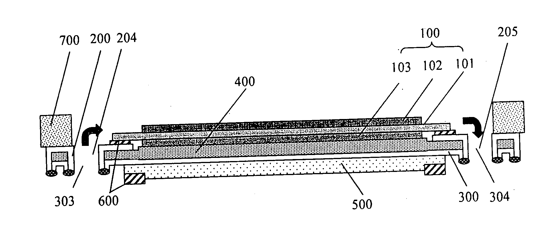
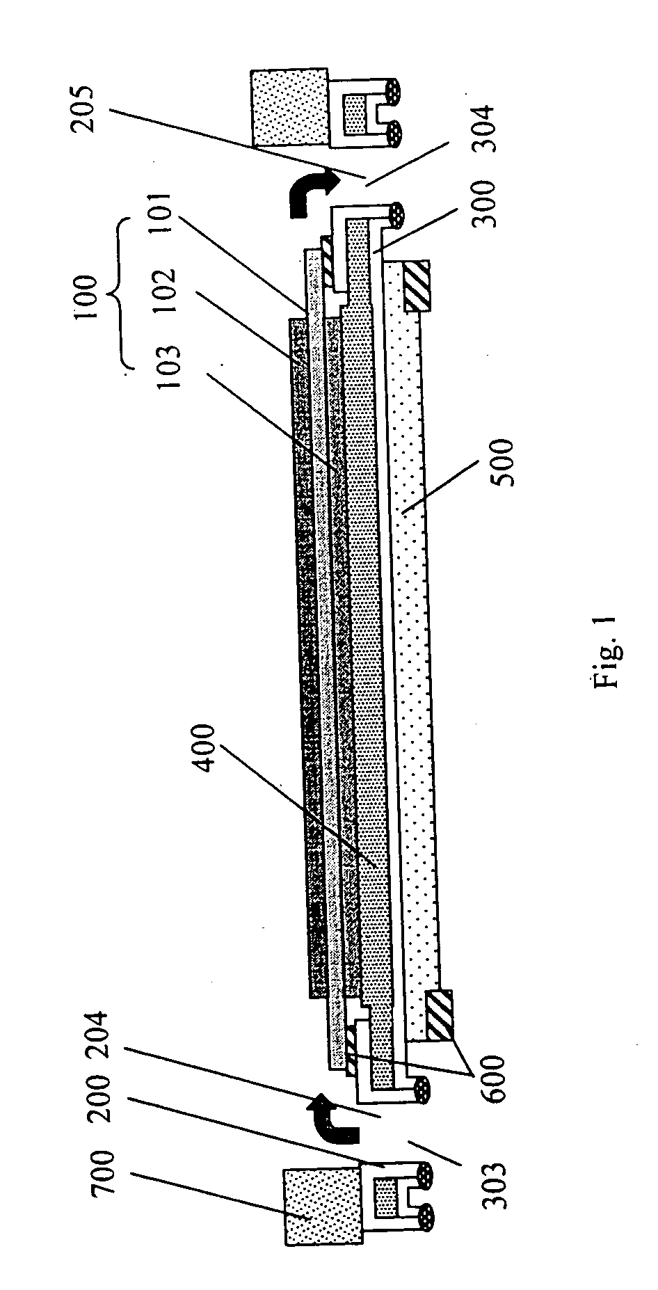
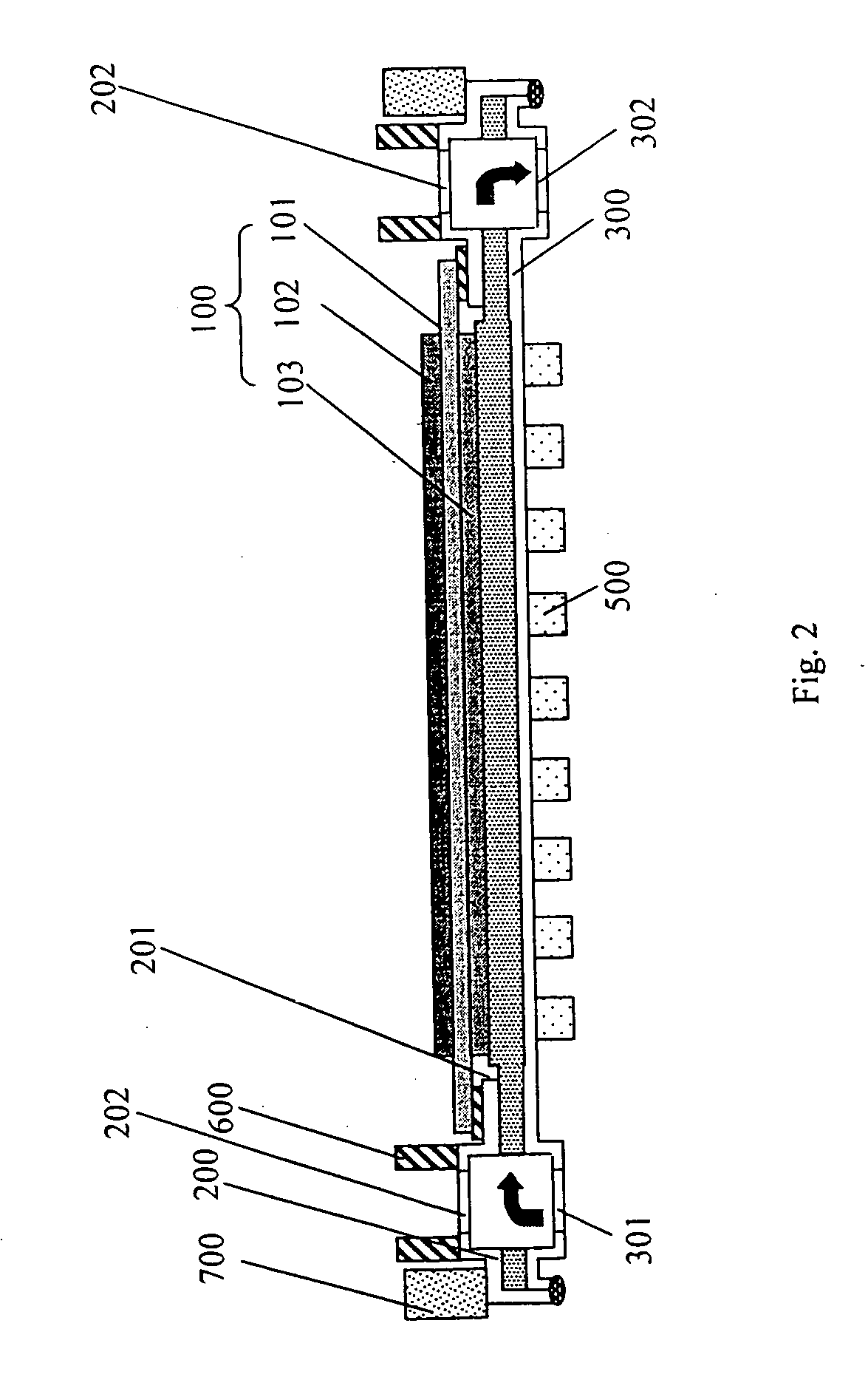
[0044] In FIG. 1 there is shown a schematic longitudinal section and in FIG. 2 a schematic cross-section of a fuel cell unit having a CEA unit (100), comprising an electrolyte (101), an anode (102) and a cathode (103), a CEA mounting element (200), comprising a shaped metal sheet with through-opening for the anode (102) and openings for a combustible gas supply (202) and combustible gas discharge (203) and also openings for air supply (204) and air discharge (205), a base plate (300), comprising a shaped metal sheet with openings for combustible gas supply (301) and combustible gas discharge (302) and also openings for air supply (303) and air discharge (304), a gas distributor element (400), comprising a pre-compressed wire mesh or metal sheet and webs (500) on a base plate surface, comprising an electrically conductive material.

[0045] The plan view on a CEA mounting element 200 and on a base plate 300 is represented schematically in FIGS. 3 and 4.

[0046] On the CEA unit 100 there...


PUM


Abstract

The invention relates to a planar fuel cell unit comprising a cathode-electrolyte-anode unit (KEA unit, 100), a gas distributor element (400), inner contacting elements, sealing elements (600, 700), and an interconnector. The interconnector is formed by a KEA fixing element (200), a base plate (300), and a gas distributor element (400). The KEA fixing element (200) and the base plate (300) are embodied as sheet metal parts that form two shells of a housing and enclose the gas distributor element (400) in a gas-tight manner. Webs (500) that are made of an electrically conductive material are applied to/configured on an external surface of the base plate.

Description

[0001] This is a nationalization of PCT / DE2004 / 001932 filed 24 Aug., 2004 and published in German.[0002] The present invention relates to a planar fuel cell unit on which a cathode-electrolyte-anode unit (subsequently termed CEA unit), a gas distributor element, elements for the internal contact, sealing elements and an interconnector are present. APPLICATION FIELD [0003] The invention is applied in energy conversion / storage by means of electrochemical generators, in particular by means of solid electrolyte fuel cells and electrolytic cells for operating temperatures from 500 to 1,000° C. STATE OF THE ART [0004] Planar fuel cell units are known from the state of the art. As a rule, a plurality of such fuel cell units is combined to form a stack in which the fuel cell units follow each other along a stacking direction. [0005] During operation of the fuel cell unit, electrochemical reactions take place in the electrodes of the CEA unit, as a result of which electrons are released in t...

Claims


Application Information

Patent Timeline
IPC IPC(8): H01M4/00H01M8/02
CPCH01M8/0202H01M8/0206H01M8/0228H01M8/0232H01M8/0247H01M8/026H01M8/0271Y02E60/50
Inventor KUZNECOV, MIHAILEICHLER, KLAUSOTSCHIK, PETER
Owner FRAUNHOFER GESELLSCHAFT ZUR FOERDERUNG DER ANGEWANDTEN FORSCHUNG EV
Why Eureka
Try Eureka