

Method and apparatus for performance and policy analysis in distributed computing systems
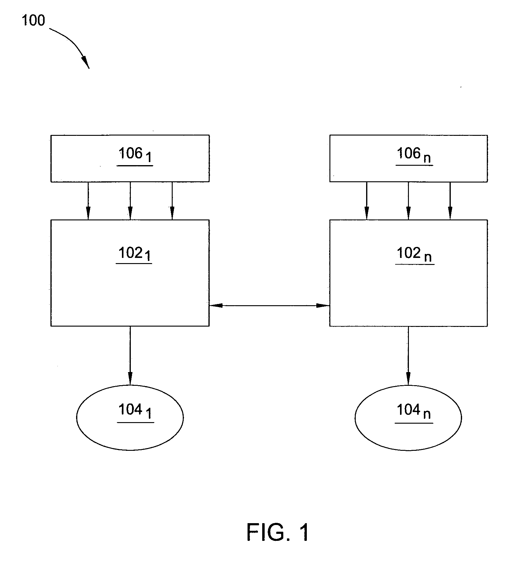
a distributed computing and policy analysis technology, applied in the field of computing systems, can solve the problems of difficult to quantify the overall system b>100/b> and the ability to process workloads b>106/b>
- Summary
- Abstract
- Description
- Claims
- Application Information
AI Technical Summary
Benefits of technology
Problems solved by technology
Method used
Image

Examples
Embodiment Construction
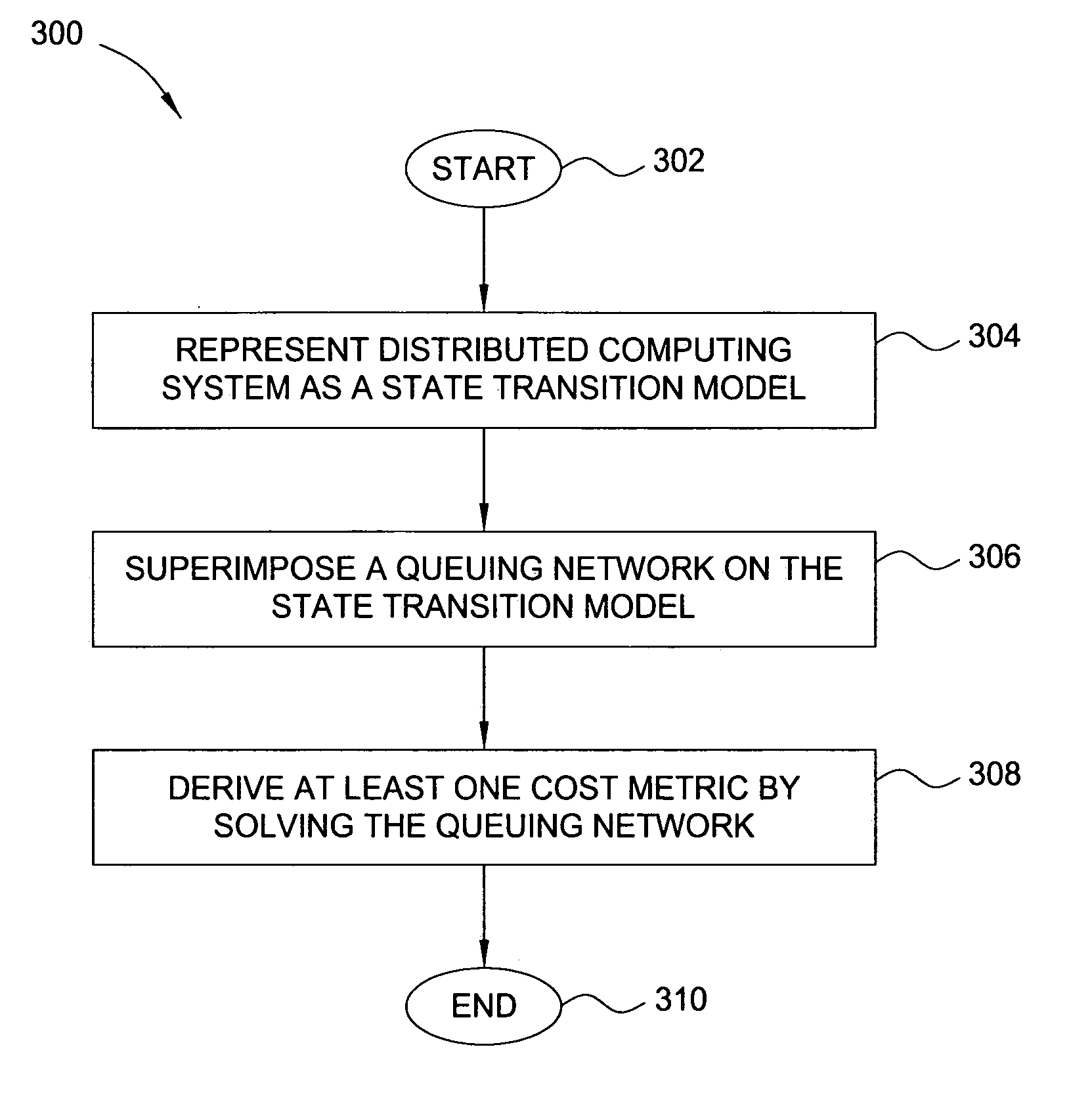
[0014] In one embodiment, the present invention is a method and apparatus for performance and policy analysis in distributed computing systems. Embodiments of the present invention make it possible to efficiently analyze the effects of various resource sharing policies, applicable to individual computing sites, on the performance of an overall distributed computing system including the computing sites.
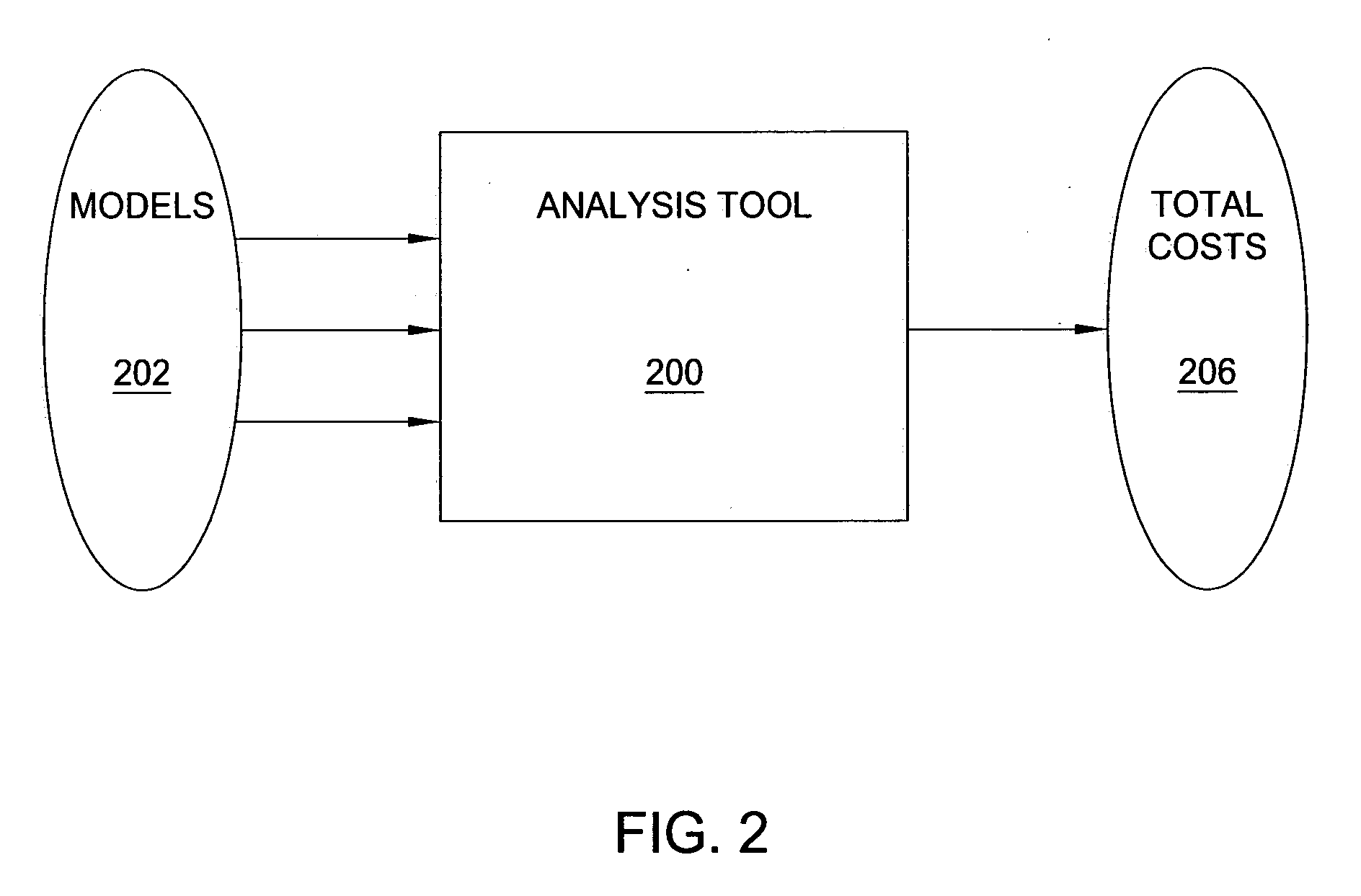
[0015]FIG. 2 is a schematic diagram illustrating one embodiment of an analysis tool 200 for analyzing a collection of resource sharing policies associated with a distributed computing system, according to the present invention. As illustrated, the analysis tool 200 is adapted to receive a plurality of inputs related to the distributed computing system and process these inputs in order to provide information from which a user can determine whether existing resource-sharing policies associated with the distributed computing system are acceptable.
[0016] In the embodiment illustrated, th...
PUM
 Abstract
Description
Claims
Application Information