
Knee Pad Construction

a knee pad and construction technology, applied in the field of knee pads, can solve the problem that the knee pads do not compensate for the distinction between the knee pads thus are typically not suitable for left and right knees, so as to facilitate the movement of gel material and facilitate the maintenance of the knee pad construction

Inactive Publication Date: 2007-05-31
BIG TIME PROD LLC
View PDF4 Cites 8 Cited by
  • Summary
  • Abstract
  • Description
  • Claims
  • Application Information

AI Technical Summary

Benefits of technology

[0009] Briefly, the present invention comprises a knee pad construction which includes a molded outer protective shell, casing or case affixed to or attachable to an interior pad assembly which has a generally convex outside surface and a generally concave inside shape into which the knee of an individual will fit. Typically, the interior pad assembly comprises a molded, flexible element or core in the form of a trough which is open at one end and closed at the opposite end and also which includes an interior cavity or recess sized and shaped for receipt of a flowable gel insert. In a preferred embodiment, a protective sheet of plastic material is fitted over or encapsulates the gel insert on the inside of the molded core. A further layer of fabric is then fitted over the plastic sheet and covers the inside face of the inside of the core element. The shape and size of the cavity or recess into which the gel insert is fitted relative to the shape and size of the gel insert itself is chosen to accommodate movement of the gel in a manner which permits the gel material to surround and cushion the knee of an individual placed against or on the gel insert. Also multiple gel inserts may be used. As an aspect of the invention, the cushion element, or core, which includes the shaped cavity and the recess, is provided with a peripheral lip to facilitate maintenance of the knee pad construction in position over the knee of an individual. The knee pad construction is designed to fit either the left knee or alternatively the right knee of an individual by providing a recess within the cushion element or core which is especially shaped to accommodate either the left knee or the right knee, as the case may be, and thus has a profile or shape which facilitates movement of the gel material in a manner that most effectively cushions the left or right patella or kneecap of an individual using the knee pads.
[0010] Thus, it is an object of the invention to provide an improved knee pad construction.
[0011] It is a further object of the invention to provide a knee pad construction which combines a concave elastic cushion member with a gel insert on the concave inside surface of the shaped elastic cushion member and layers of material to facilitate maintenance of the gel insert in a desired and appropriate position in the knee pad.
[0012] Another object of the invention is to provide a knee pad construction which will beneficially accommodate the left knee of an individual and a separate knee pad construction to accommodate the right knee of an individual.
[0013] Another object of the invention is to provide a knee pad construction which provides comfort to the user and which further includes means to insure appropriate positioning of the knee pad on the individual as well as maintenance of such a position on an individual.
[0014] A further object of the invention is to provide a knee pad having a rugged construction that is economical to manufacture, easy to use, lightweight and capable of use for a wide variety of knee sizes and shapes.

Problems solved by technology

Such knee pads thus typically do not compensate for the distinction between left and right knees, or for the sizing of the knee of an individual.

Method used


Image

  • Knee Pad Construction
  • Knee Pad Construction
  • Knee Pad Construction

Examples


Embodiment Construction

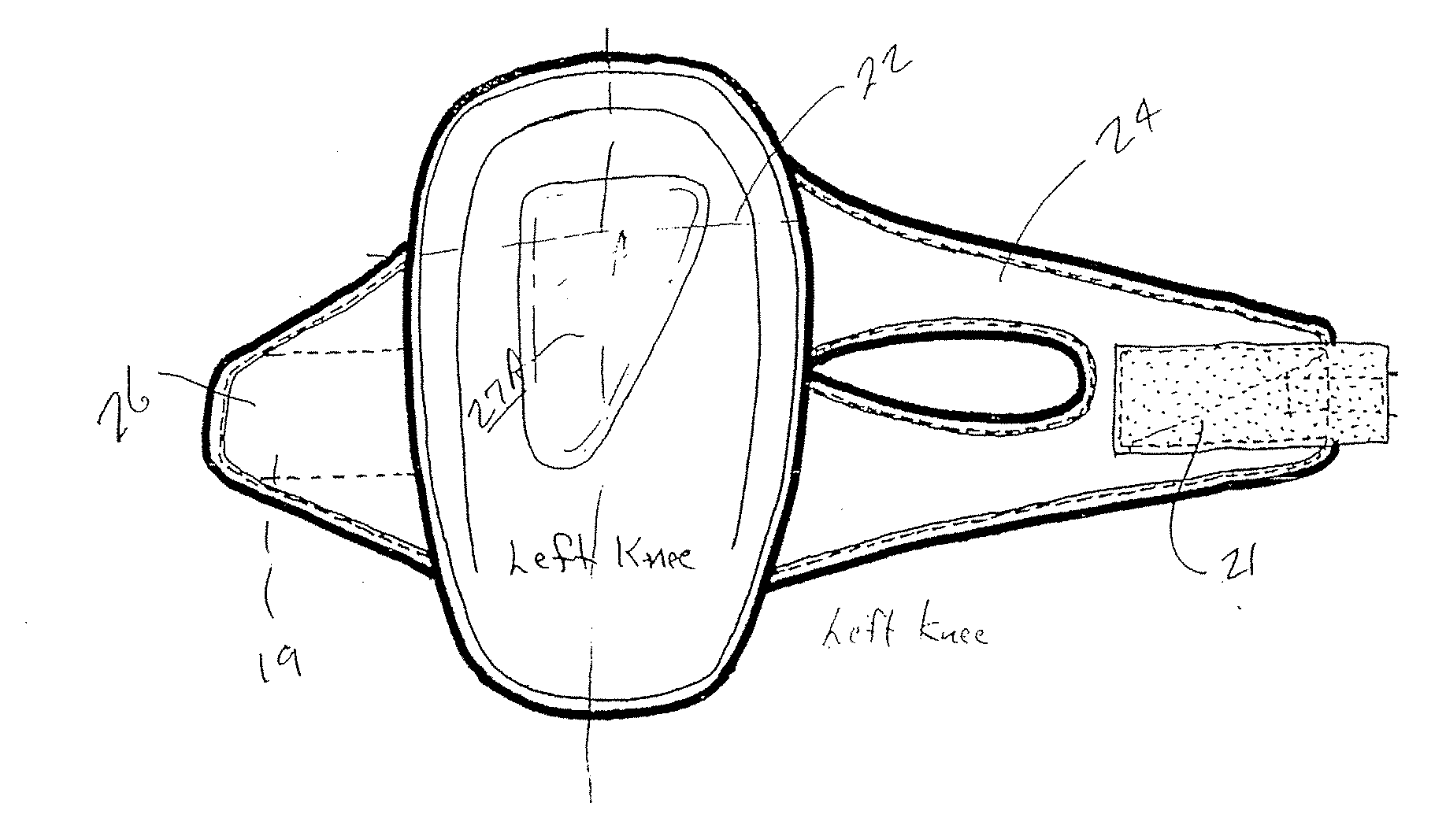
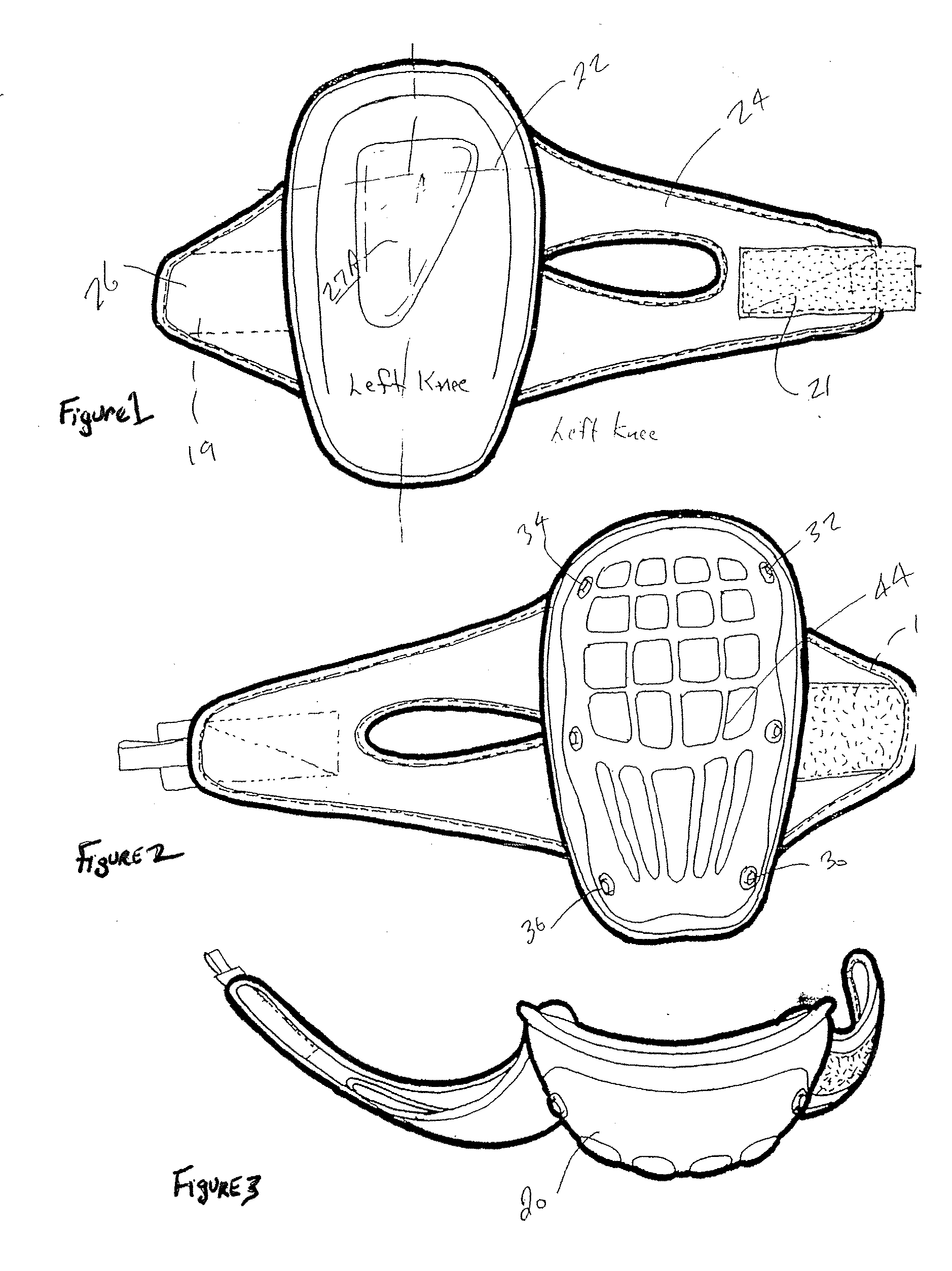
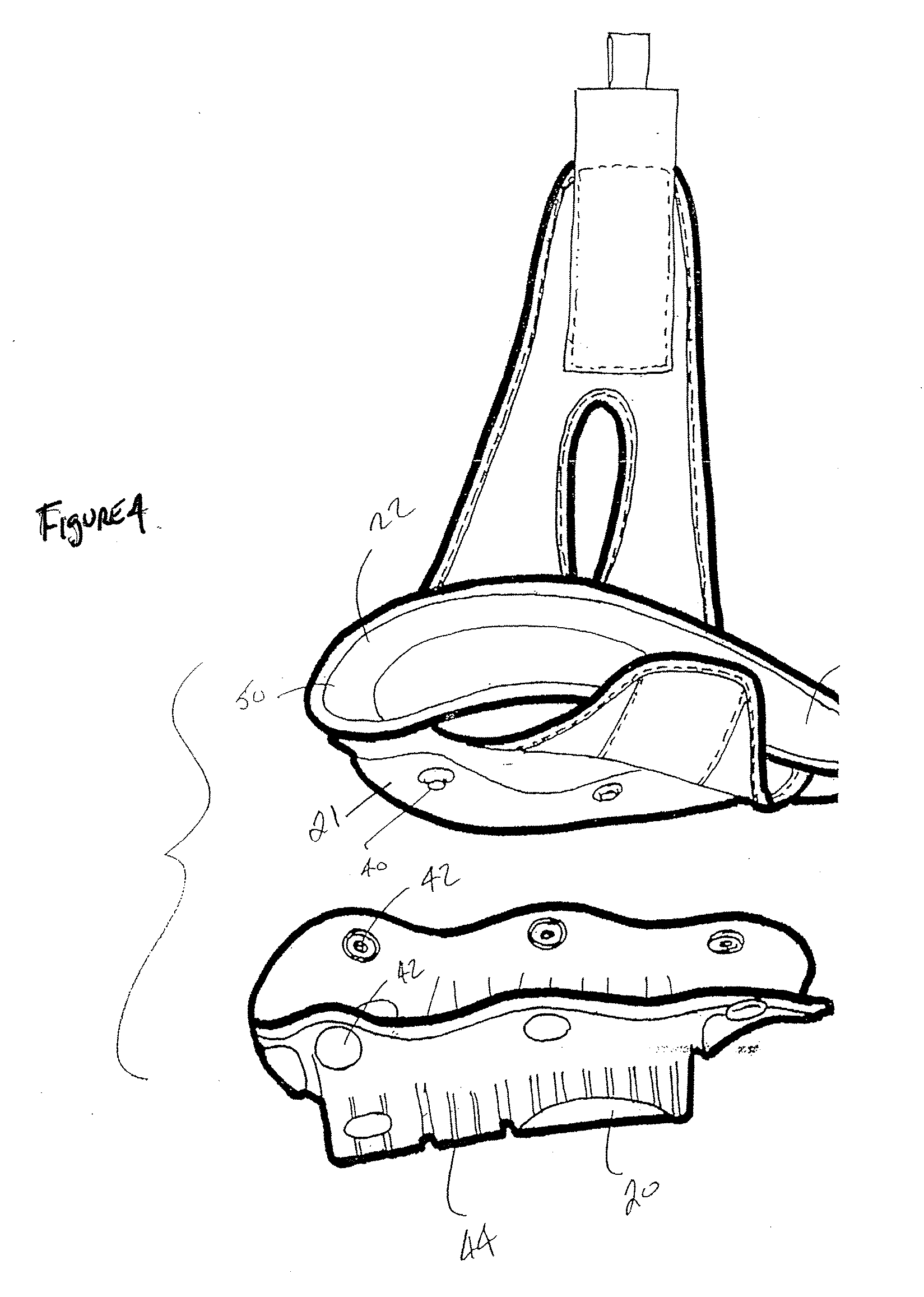
[0039] Referring to the figures, and in particular FIG. 4, a preferred embodiment of a knee pad assembly of the invention is generally comprised of two basic components. The first component is an outer shell or casing or case 20. The second basic component is an inner, shaped cushion element, pad assembly or core 22 (See FIGS. 1-3) which includes a strap construction, for example, strap 24 and compatible strap attachment 26. The casing or shell or case 20 is affixed to the shaped cushion element 22 to provide a hard outer layer or shell which is designed to engage against a surface, such as a floor. The hard outer casing or shell 20 is typically attached by means of snaps, for example, snaps 30, 32, 34 and 36 to the interior shaped cushion element 22. That is, an external convex surface 21 of the cushion element 22 includes snap members 40 compatible with snap members such as snap member 42 of shell 20, for attachment of the shell or casing or outer member 20 to the cushion element ...


PUM


Abstract

A knee pad construction includes a shaped cushion element with a concave interior with a recess having a flowable gel insert therein. The recess and insert are shaped to accommodate the left knee or the right knee of an individual.

Description

CROSS REFERENCE TO RELATED APPLICATION [0001] This is a divisional application of Ser. No. 10 / 943,347 filed Sep. 17, 2004, which is continuation in part application of Ser. No. 10 / 926,240 filed Aug. 25, 2004, both of which are incorporated herewith by reference and for which priority is claimed. BACKGROUND OF THE INVENTION [0002] The present invention relates to a protective knee pad construction and, more particularly, to a pair of kneepads which are constructed to accommodate, respectively, the left knee and the right knee of an individual. [0003] Protective knee pads are used by various individuals, for example, construction workers, mechanics, sportsmen, athletes, and others who find it necessary to protect their knees as a result of their work or activities. Utilization of protective knee pads placed on or around the knee for use when kneeling on hard surfaces is thus a common practice and, in some instances, a requirement in order to practice a trade or craft. Various knee pad...

Claims


Application Information

Patent Timeline
Patent Type & Authority Applications(United States)
IPC IPC(8): A41D13/06
CPCA41D13/0568A41D13/065A63B71/081A63B71/1225A63B2071/125A63B2209/10
Inventor GODSHAW, DONALD E.
Owner BIG TIME PROD LLC
Learn More