
Covered rain gutter system

Inactive Publication Date: 2007-05-31
PIJANOWSKI WALTER
View PDF29 Cites 22 Cited by
  • Summary
  • Abstract
  • Description
  • Claims
  • Application Information

AI Technical Summary

Benefits of technology

[0014] A feature and advantage of the present invention is its ability to facilitate uniform gutter support via secure mounting to the facia board.
[0015] Another feature and advantage of the present invention is its ability to be easily installed.
[0016] Another feature and advantage of the present invention is its ability to maintain gutter positioning close to the support structure, thereby limiting water creepage therebehind.
[0017] Yet another feature and advantage of the present invention is its ability to essentially eliminate the collection of unwanted debris.
[0018] Yet another feature and advantage of the present invention is its ability to facilitate easy access behind the gutter rainwater collection compartment.
[0019] Still another feature and advantage of the present invention is its ability to be mounted to facia below the extended end of a roof.

Problems solved by technology

Numerous types of gutters are available for use, wherein a common problem to many, if not all such rain collection devices is the undesirable accumulation of debris and the resulting inhibition from proper functioning.
Further, once cluttered with debris, most current designs do not facilitate cleaning, especially those adapted with covers.
Although such screens and / or grates can prevent leaves or other debris from entering the gutter rainwater collection compartment, accumulated debris on top of the screens and / or grates can become a problem because collected rainwater must pass through these grates or screens to enter the main gutter compartment.
Unfortunately, relying solely on such forces does not prevent the passage of all debris.
This phenomenon can result in rainwater creeping behind the gutter, potentially causing water damage to the structure.

Method used


Image

  • Covered rain gutter system
  • Covered rain gutter system
  • Covered rain gutter system

Examples


Embodiment Construction

[0030] In describing the preferred and alternate embodiments of the present invention, as illustrated in the figures and / or described herein, specific terminology is employed for the sake of clarity. The invention, however, is not intended to be limited to the specific terminology so selected, and it is to be understood that each specific element includes all technical equivalents that operate in a similar manner to accomplish similar functions.

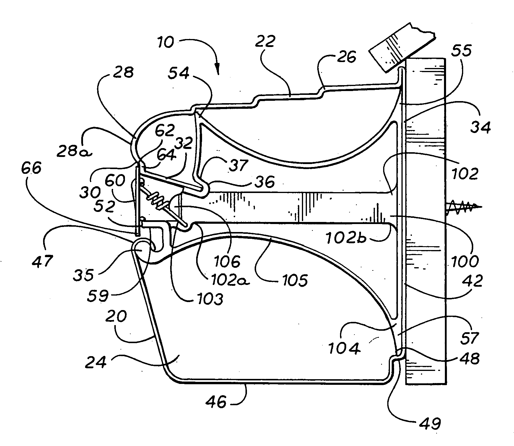
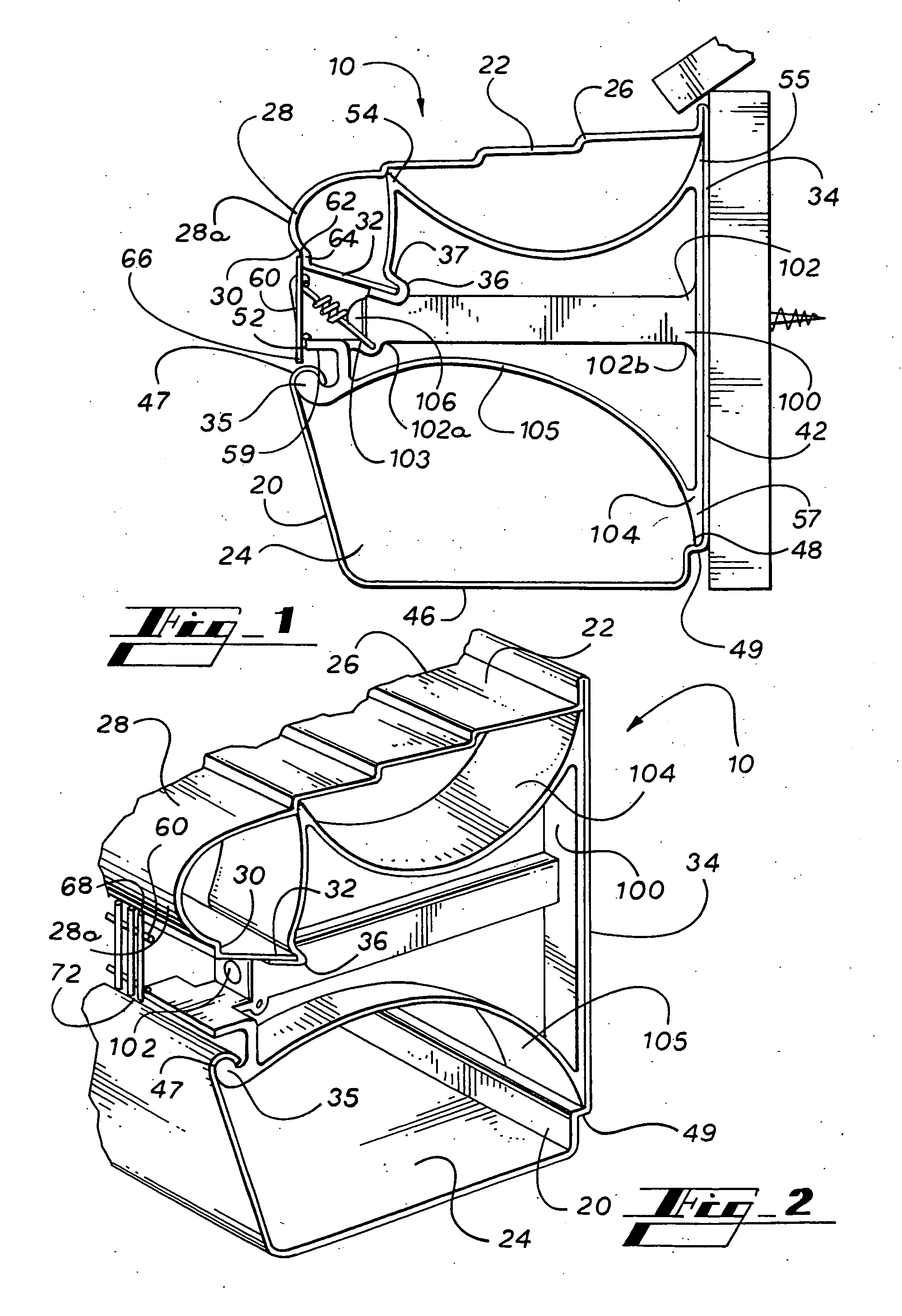
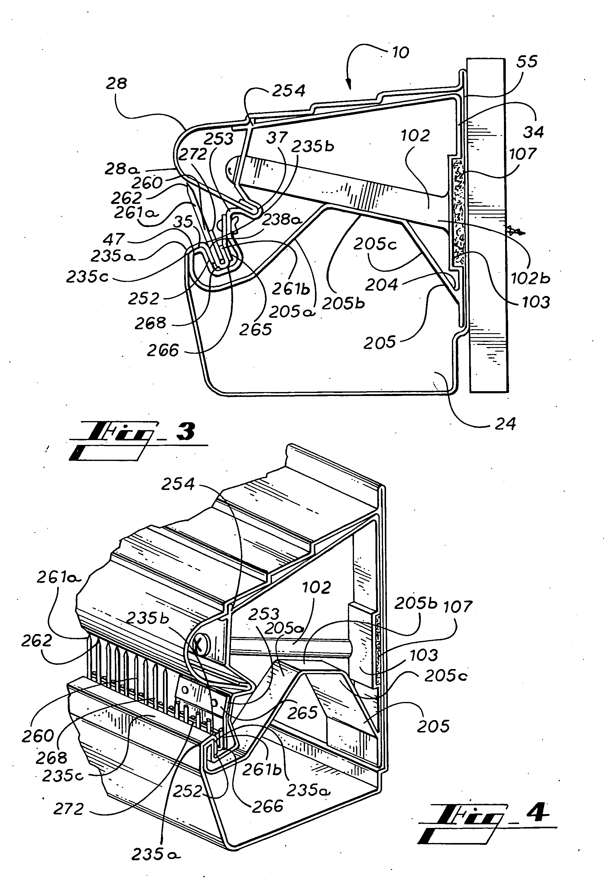
[0031] Referring now to FIGS. 1-2, the present invention in the preferred embodiment is covered rain gutter system 10, comprising multi-compartment gutter unit 20, grate member 60, and mount system 100. Preferably, multi-compartment gutter unit 20 is defined by upper cover 22 and lower rainwater collection compartment 24, wherein grate member 60 extends therebetween, wherein mount system 100 is defined by internal fastener port 102, bracket support frame 104, and threaded fastener 106, and wherein internal fastener port 102 is defined to ext...


PUM


Abstract

A covered, multi-compartment rain gutter that mounts to facia to collect water upon exit from the peripheral edge of a roof structure, wherein surface dynamics facilitate the collection of rainwater and minimize the passage of undesirable debris, and wherein a straining member further limits the passage of debris into the gutter collection compartment.

Description

[0001] This application is a continuation-in-part of co-pending U.S. Utility patent application Ser. No. 11 / 234,589, filed Sep. 23, 2005, entitled “Covered Rain Gutter System,” and to the fullest extent permitted by law, claims priority to and the benefit thereof.FIELD OF THE INVENTION [0002] The present invention relates generally to rain water collection devices, and more particularly, to a one-piece rain gutter and cover unit, wherein the gutter is a three-dimensional structure that receives water from a mounted position under the extended end of a roof, wherein a springedly-held grating system essentially eliminates clogging of downspouts by inhibiting the accumulation of leaves, and wherein an integrated mounting system provides secure placement and support for the grating and the gutter. BACKGROUND OF THE INVENTION [0003] Numerous types of gutters are available for use, wherein a common problem to many, if not all such rain collection devices is the undesirable accumulation of...

Claims


Application Information

Patent Timeline
IPC IPC(8): E04D13/00
CPCE04D13/064E04D13/0727E04D13/076E04D13/0725
Inventor PIJANOWSKI, WALTER
Owner PIJANOWSKI WALTER
Learn More