
Apparatus for accommodating greater height variance of articles in shrink packaging machine

a technology of shrink packaging machine and apparatus, which is applied in the direction of bundling machine details, packaging goods type, bundling articles, etc., can solve the problems of deformation or bending of articles, inability to easily deploy the approach of existing shrink packaging machines, and high cost of two synchronized conveyers

Inactive Publication Date: 2007-05-31
KPCMASTERS CRAFT INT
View PDF9 Cites 7 Cited by
  • Summary
  • Abstract
  • Description
  • Claims
  • Application Information

AI Technical Summary

Benefits of technology

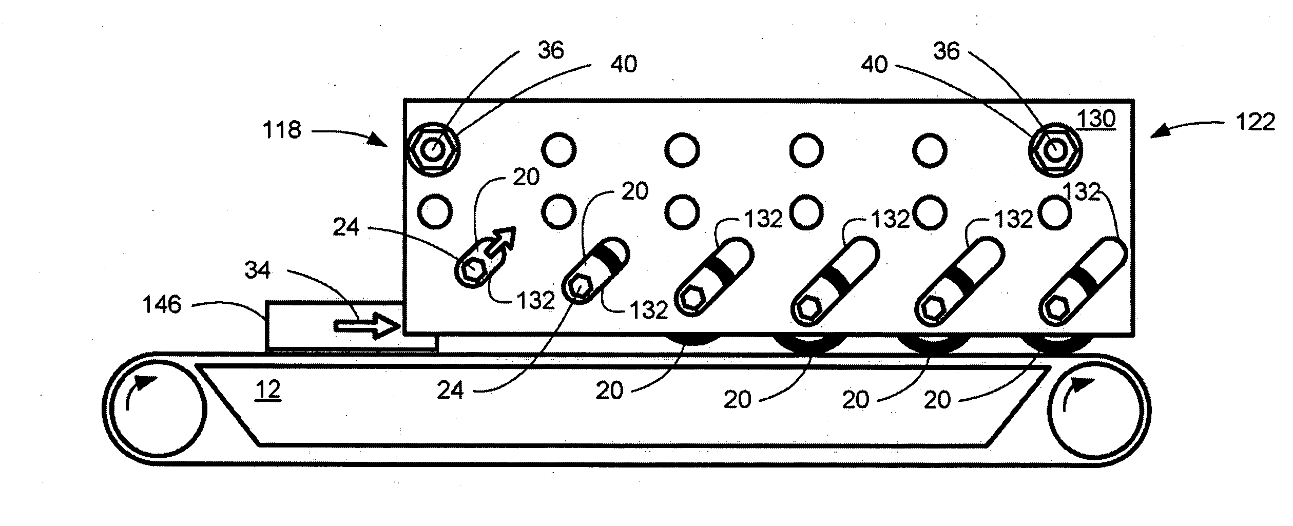
[0039] In a feature of this aspect, the slot length of each a first subset of the plurality of slots is less than a slot length of each of a second subset of the plurality of slots. Each subset of slots may include only a single slot or a plurality of slots.
[0040] In yet another feature, the slot length of each a first subset of the plurality of slots is less than a slot length of each of a second subset of the plurality of slots; the slot length of each of the second subset of the plurality of slots is less than a slot length of each of a third subset of the plurality of slots; the side members have opposed ends in the first, horizontal direction; and the first subset of slots is disposed closer to a first the opposed end of the side members than the second subset of slots, and the second subset of slots is disposed closer to the first opposed end of the side members than the third subset of slots.
[0041] In another feature, the lowermost position of one of the rollers is selectively adjustable. In this respect, the lowermost position of one of the rollers may be defined by a blocking member that is adjustably positionable. For example, the blocking member may comprise an arm that is pivotably mounted and that extends adjacent to one or more of the slots. Alternatively, the blocking member may comprise an insert that is adapted to be removably disposed within the slot and the inert may be chosen from one of a plurality of differently sized inserts. For example, the inserts may have different lengths for selectively limiting the range of movement of rollers within the slots.

Problems solved by technology

If the article happens to be thin, then pressure exerted on the article by the shrinking film tends to cause deformation or bending of the article.
Additionally, if the article happens to be lightweight, then turbulent air blown within the hot air chamber tends to cause the article to float or otherwise lift off of the conveyor and move around within the chamber, which is undesirable.
The use of two synchronized conveyers is fairly expensive and requires resetting of the distance between the two conveyers whenever an article having a new thickness is to be shrink wrapped.
Furthermore, such an approach can not be readily deployed in existing shrink packaging machines that are not built to accommodate this approach.

Method used


Image

  • Apparatus for accommodating greater height variance of articles in shrink packaging machine
  • Apparatus for accommodating greater height variance of articles in shrink packaging machine
  • Apparatus for accommodating greater height variance of articles in shrink packaging machine

Examples


Embodiment Construction

[0067] As a preliminary matter, it will readily be understood by one having ordinary skill in the relevant art (“Ordinary Artisan”) that the present invention has broad utility and application. Furthermore, any embodiment discussed and identified as being “preferred” is considered to be part of a best mode contemplated for carrying out the present invention. Other embodiments also may be discussed for additional illustrative purposes in providing a full and enabling disclosure of the present invention. Moreover, many embodiments, such as adaptations, variations, modifications, and equivalent arrangements, will be implicitly disclosed by the embodiments described herein and fall within the scope of the present invention.

[0068] Accordingly, while the present invention is described herein in detail in relation to one or more embodiments, it is to be understood that this disclosure is illustrative and exemplary of the present invention, and is made merely for the purposes of providing ...


PUM


Abstract

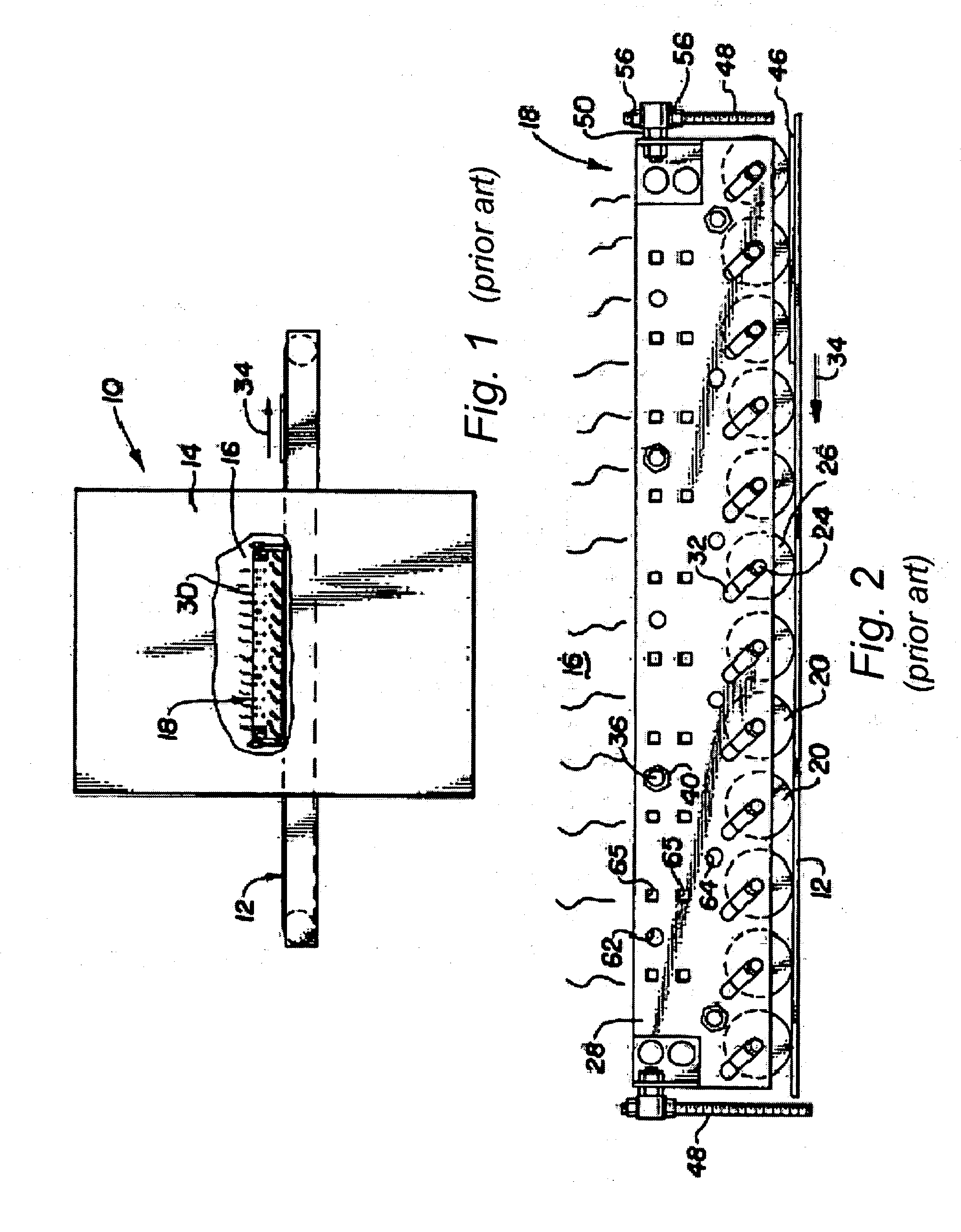
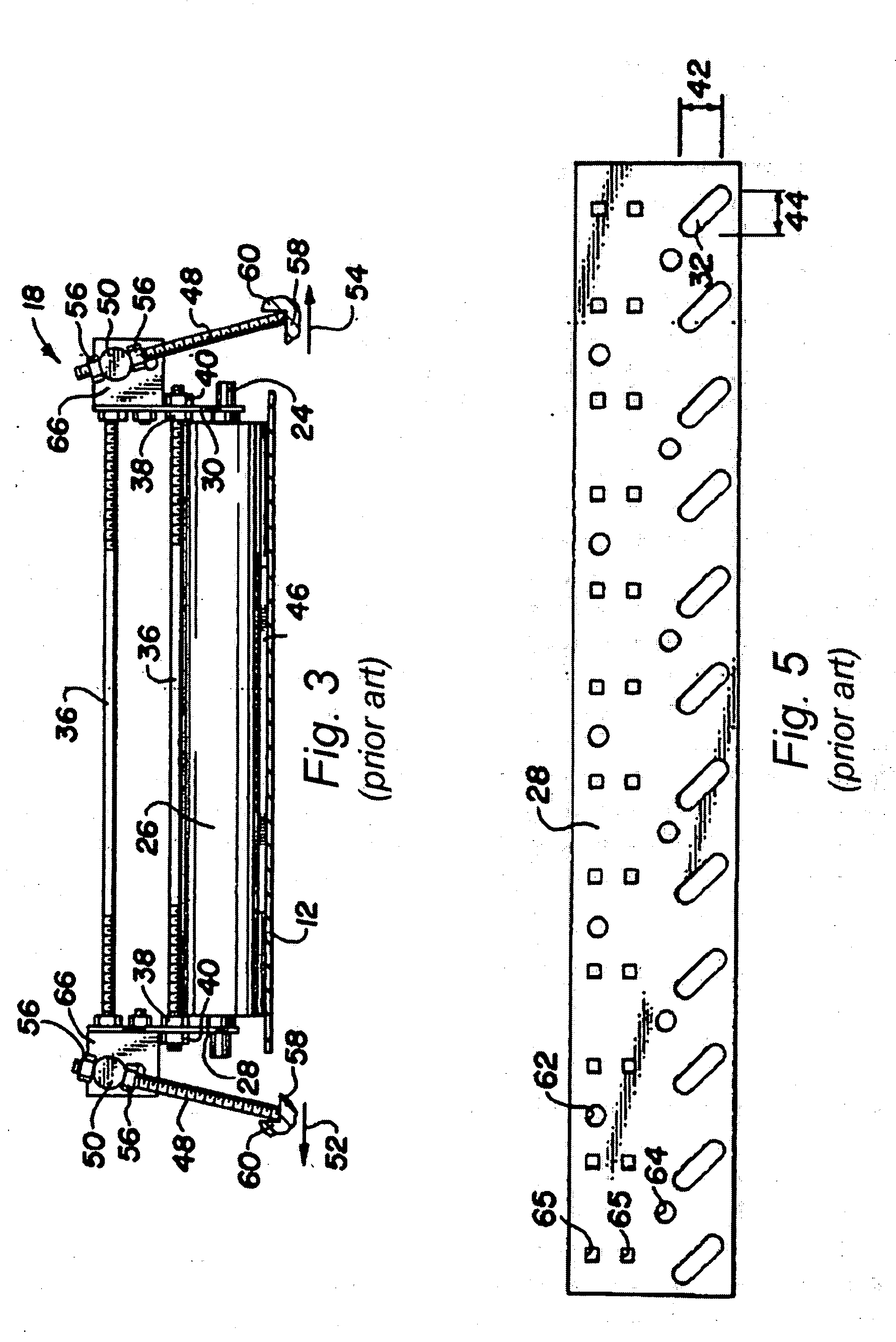
An apparatus for use in a shrink packaging machine for accommodating a greater height variance of articles includes: rollers, each roller including a shaft and a cylinder on the shaft for rotation about an axis of the shaft; and a frame including a pair of parallel side members generally extending in a first, horizontal direction and defining slots receiving opposite ends of the shafts for mounting of the rollers there between. Each of the slots has a slot length that extends in horizontal and vertical directions, and the rollers each generally extends in a third direction orthogonal both to the horizontal and vertical directions. Furthermore, each of the rollers is received within a pair of the slots and is vertically and horizontally displaceable and, when each roller is disposed at its respective lowermost position, the axes of the rollers do not all lie within a horizontal plane.

Description

COPYRIGHT STATEMENT [0001] All of the material in this patent document is subject to copyright protection under the copyright laws of the United States and other countries. The copyright owner has no objection to the facsimile reproduction by anyone of the patent document or the patent disclosure, as it appears in official governmental records but, otherwise, all other copyright rights whatsoever are reserved. BACKGROUND OF THE INVENTION [0002] The present invention relates generally to shrink packaging machines and, in particular, to shrink packaging machines for shrink wrapping thin or lightweight articles including, for example, easily deformed, bent, or folded articles that are thin or light weight, and that have a range of various heights. [0003] In shrink wrapping articles, it is common to entirely cover each article top and bottom with a shrink film, such as polyvinyl chloride or polypropylene soft shrink material, and then transport the article covered in shrink film on a me...

Claims


Application Information

Patent Timeline
Patent Type & Authority Applications(United States)
IPC IPC(8): B65G13/02
CPCB65B59/02B65G21/2054B65B53/06B65B59/005B65B59/001
Inventor ANDERSON, RICHARDBOCKUS, JEFF
Owner KPCMASTERS CRAFT INT
Learn More