Vibration damping unit

a technology of vibration damping and damping unit, which is applied in the direction of shock absorbers, mechanical equipment, and support structure mounting, etc., can solve the problems of workers being released from troublesome works, and achieve the effect of preventing the sway of an existing rack

Inactive Publication Date: 2007-05-31
FUJITSU LTD
View PDF17 Cites 26 Cited by
  • Summary
  • Abstract
  • Description
  • Claims
  • Application Information

AI Technical Summary

Benefits of technology

[0006] It is accordingly an object of the present invention to provide a vibration damping unit contributing to prevention of the sway of an existing rack in a facilitated manner.
[0008] The support body of the vibration damping unit is removable from the rack. The vibration damping unit can be mounted on an existing rack in a facilitated manner without any change in the design of the rack. Workers can be released from troublesome works, such as moving the rack, even when the vibration damping unit is applied to the rack. The means for preventing sway or vibration can be applied to the rack even when an electronic apparatus, including a disk array apparatus and the like, is in operation inside the rack.
[0009] The mass is supported on the support body for movement along an imaginary plane. The elastic member is interposed between the support body and the mass. The elastic member serves to realize the reciprocation of the mass along the imaginary plane. The reciprocation of the mass contributes to a significant suppression of the sway or vibration of the rack when the rack suffers from an earthquake, for example. The rack is allowed to have a smaller rigidity. The assembling process can be simplified. The simplified process leads to a reduction in the production cost of the rack. A reduction in the rigidity greatly contributes to a significant reduction in the weight of the rack.

Problems solved by technology

Workers can be released from troublesome works, such as moving the rack, even when the vibration damping unit is applied to the rack.

Method used


Image

  • Vibration damping unit
  • Vibration damping unit
  • Vibration damping unit

Examples


Embodiment Construction

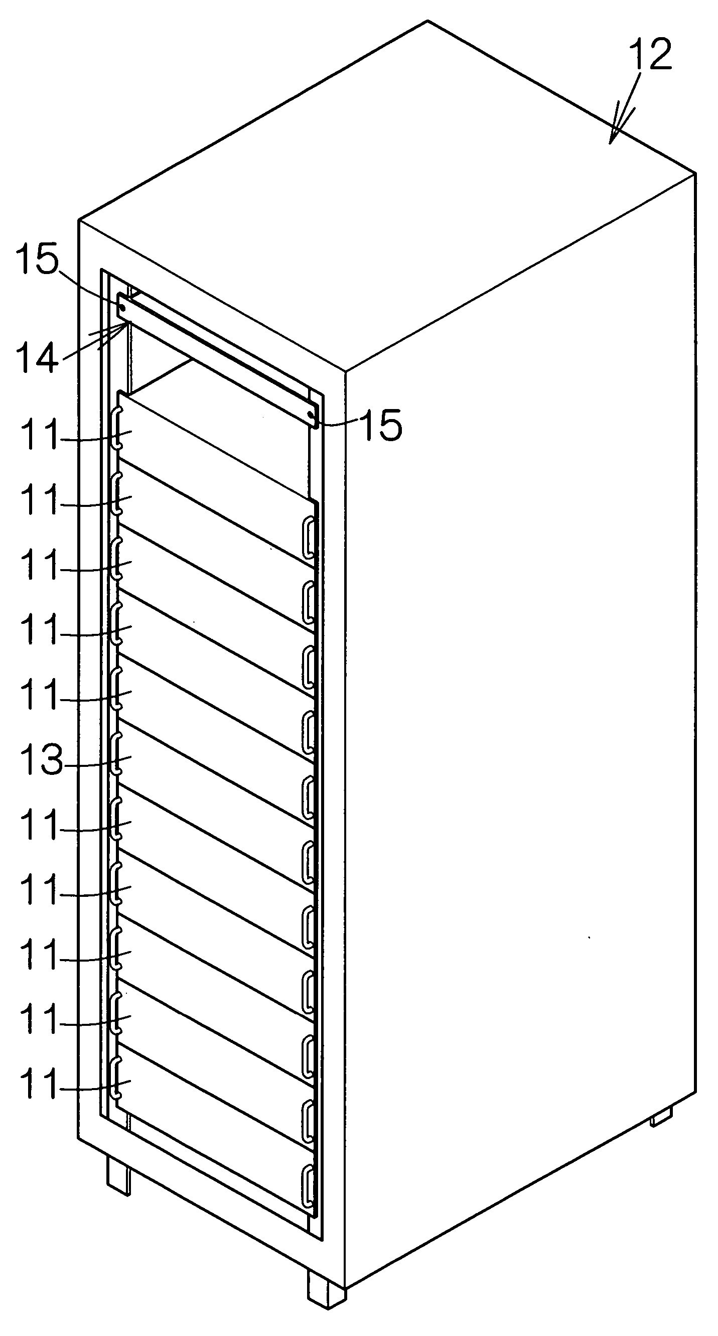
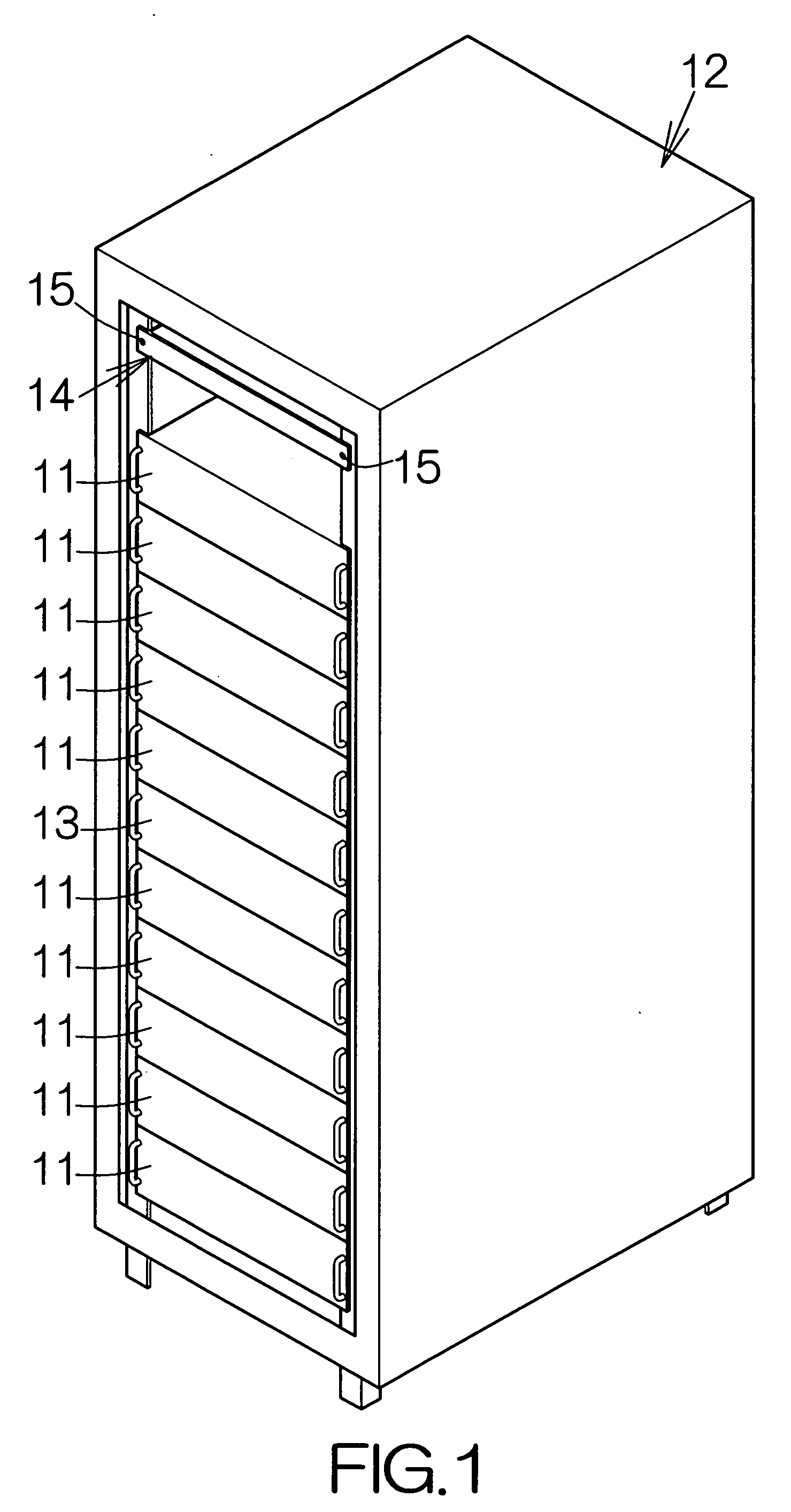
[0024]FIG. 1 schematically illustrates a rack 12 containing a rack-mounted disk array apparatus. In this case, a plurality of disk array apparatuses 11 are mounted on the rack 12, for example. The disk array apparatuses 11 are connected to a host or server computer 13 likewise mounted on the rack 12, for example. The disk array apparatuses 11 operate in response to instruction signals supplied from the server computer 13.

[0025] As conventionally known, recording disk drives or hard disk drives (HDDs) are mounted in the individual disk array apparatus 11. The hard disk drive may include a recording disk or hard disk (HD) having the rotation axis extending in the vertical direction perpendicular to the floor, for example. In this case, each disk array apparatus 11 holds fifteen hard disk drives. Alternatively, the rotation axis of the hard disk may extend in the horizontal direction in parallel with the floor.

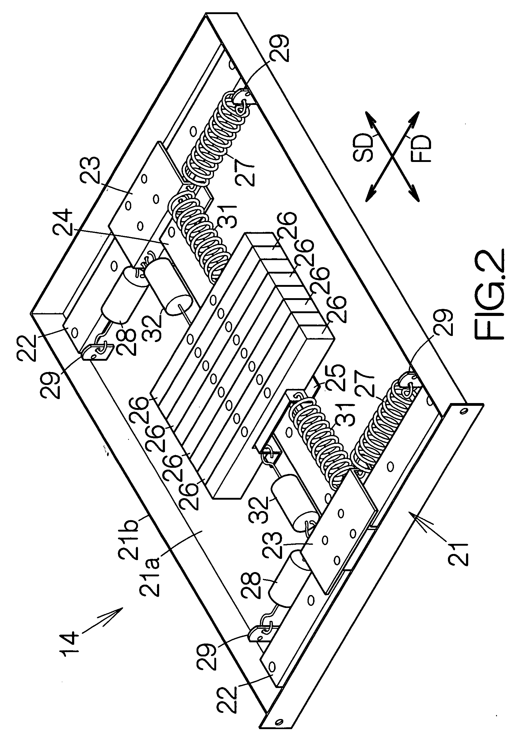
[0026] A vibration damping unit 14 is mounted on the rack 12 just below th...


PUM


Abstract

A vibration damping unit includes a rack-mounted support body removably mounted on a rack. A mass is supported on the support body for movement along an imaginary plane. An elastic member is coupled to the support body and the mass. The support body is removable from the rack. The vibration damping unit can be mounted on an existing rack in a facilitated manner without any change in the design of the rack. Workers can be released from troublesome works, such as moving the rack, even when the vibration damping unit is applied to the rack. The means for preventing sway or vibration can be applied to the rack even when an electronic apparatus, including a disk array apparatus and the like, is in operation inside the rack.

Description

BACKGROUND OF THE INVENTION [0001] 1. Field of the Invention [0002] The present invention relates to a method of preventing the sway of a rack accommodating a rack-mounted disk array apparatus, for example. [0003] 2. Description of the Prior Art [0004] A rack-mounted disk array apparatus is well known. The disk array apparatus is mounted on a rack located on a seismic isolation apparatus. The seismic isolation apparatus serves to reduce the sway of the rack. The disk array apparatus is thus allowed to keep its normal operation without any interruption. Lifting up the rack is required to place the rack on the seismic isolation apparatus. [0005] The rack weighs at least 150 kg. The disk array apparatus or apparatuses mounted in the rack serves to further increase the weight. It is quite difficult to lift up the rack onto the seismic isolation apparatus. What is worse, lifting up the rack should interrupt the operation of the disk array apparatus. In other words, once the disk array ap...

Claims


Application Information

Patent Timeline
Patent Type & Authority Applications(United States)
IPC IPC(8): A47F7/00
CPCF16F7/104H05K7/1495
Inventor HIDAKA, HIROSHIURAKI, YASUSHI
Owner FUJITSU LTD
Why Eureka
Try Eureka