
Hanging clamp for different size rods

Inactive Publication Date: 2007-05-31
LIN YU SHEN +1
View PDF8 Cites 5 Cited by
  • Summary
  • Abstract
  • Description
  • Claims
  • Application Information

AI Technical Summary

Benefits of technology

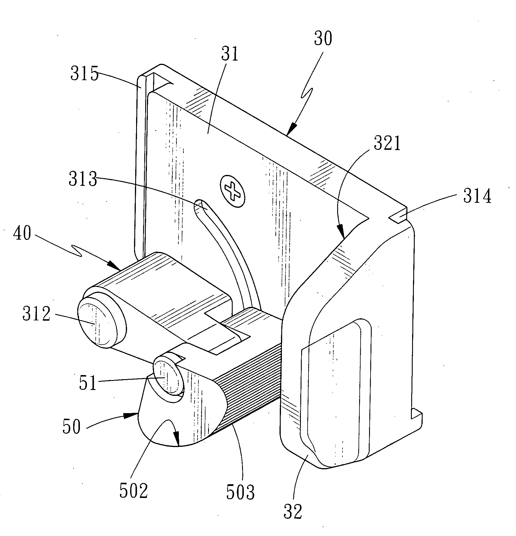
[0008] The primary objective of the present invention is to provide a hanging clamp for different size rods, which comprises a rotatory piece capable of rotating at a predetermined angle pivoted at a proper position of body by using a first pivotal axis, a clamping member also capable of rotating at a predetermined angle pivoted at one end of rotatory piece by using a second pivotal axis in such a manner that while the rotatory piece rotates around the first pivotal axis, the clamping member will be turned to clamp a rod, wherein the clamping member can clamp different size rods by using the changeable distance between the clamping member and a base, also, said changeable distance can be adjusted again by using the rotation of clamping member around the second pivotal axis. As a result, the clamping size range of hanging clamp for different size rods can be expanded by using the changeable distance of double pivotal axis.
[0009] The secondary objective of the present invention is to provide a hanging clamp for different size rods, which comprises a retaining recess formed at one end of the body of base, a retaining projection arranged at another end of body in such a manner that a plurality of hanging clamps can be assembled together to clamp a plurality of rods without manufacturing additional coupling elements. Hence, the manufacturing cost of the respective hanging clamps will be diminished.

Problems solved by technology

Conventionally, small-size rods, such as hand tools, are easy to be put away by the users due to their specific storage holders designed; however, large-size rods, such as cleaning tools, garden tools, construction tools and the like, are not easy to be put away because of their large sizes.

Method used


Image

  • Hanging clamp for different size rods
  • Hanging clamp for different size rods
  • Hanging clamp for different size rods

Examples


Embodiment Construction

[0026] Referring to FIGS. 5-7 a hanging clamp for different size rods in accordance with the present invention is shown and comprises a L-shaped base 30, a rotatory piece 40 as well as a clamping member 50, wherein a body 31 is formed on the base 30, an outwardly projected retaining portion 32 is arranged at one end of body 31, a plurality of through holes 311 for fixing the body 31 to the wall by means of a plurality of bolts 33 are respectively defined on said body 31. Moreover, a first pivotal axis 312 is mounted at a proper position of body 31, an arc-shaped slot 313 having a predetermined angle is formed on the body 31 by using said first pivotal axis 312 as its center, at one end of body 31 is provided with a retaining recess 314, while at another end of body 31 is defined with a retaining projection 315, at the retaining portion 32 in response to the first pivotal axis 312 is arranged a retaining wall 321. One end of the rotatory piece 40 for rotating around the first pivotal...


PUM


Abstract

The present invention relates to a hanging clamp for different size rods, which comprises a L-shaped base having a body, a rotatory piece capable of rotating at a predetermined angle, as well as a clamping member also capable of rotating at a predetermined angle; wherein a retaining portion projects out of one end of body, the rotatory piece is pivoted at a proper position of body by means of a first pivotal axis, while the clamping member is pivoted at one end of rotatory piece by using a second pivotal axis; furthermore, the clamping member in response to the retaining portion is provided with an arc-shaped clamping surface having a concentric circle, whereby enabling the rotatory piece pivotally rotate the clamping member to clamp different size rods, by using the changeable distance between the clamping surface and the retaining portion; prefectably, the clamping member can also pivotally rotate to increase or decrease said changeable distance between the clamping surface and the retaining portion, so as to expand the clamping size range of hanging clamp for different size rods by using the changeable distance of double pivotal axis.

Description

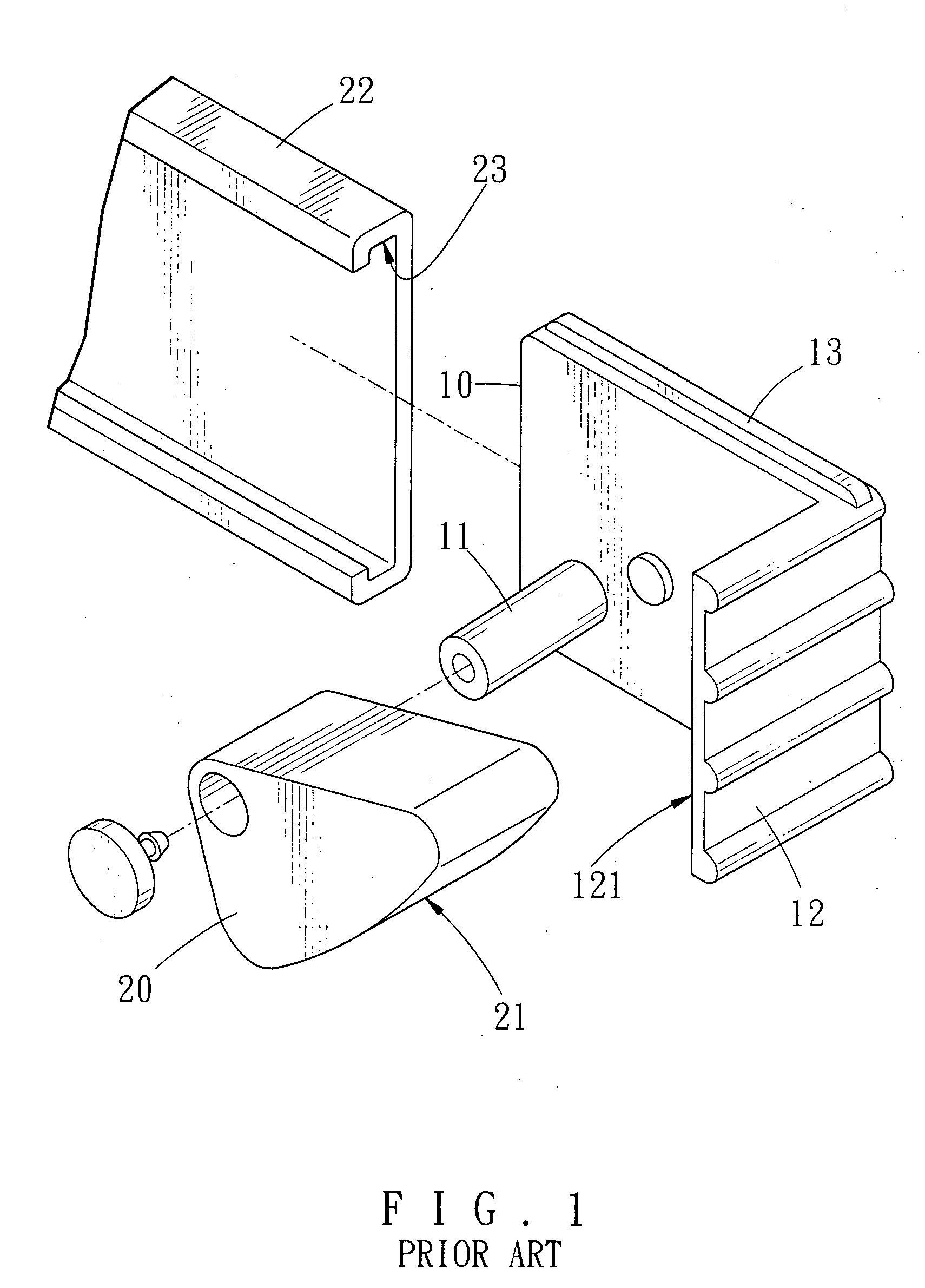
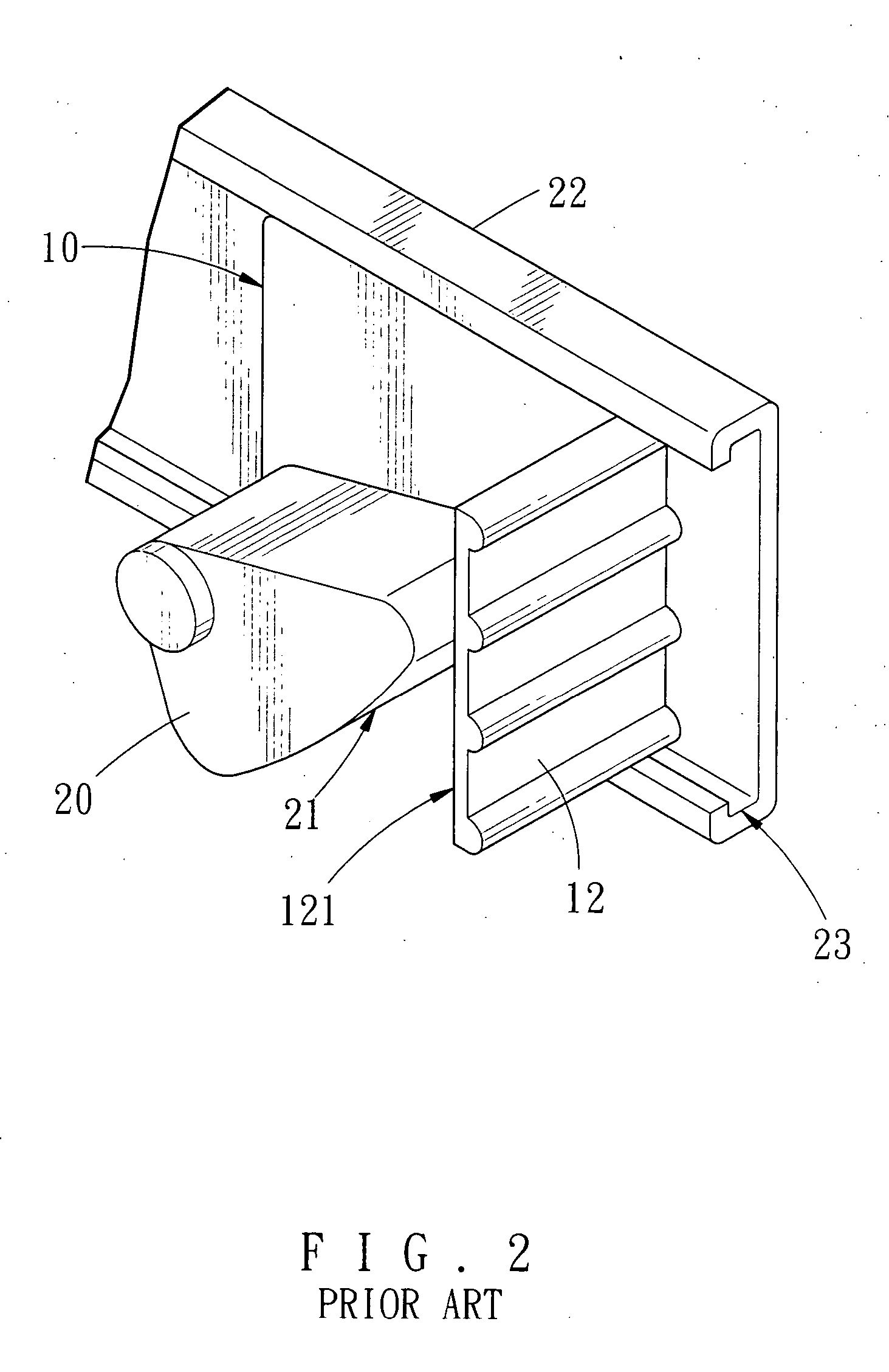
BACKGROUND OF THE INVENTION [0001] 1. Field of the Invention [0002] The present invention relates to a hanging clamp for different size rods which can expand the clamping size range of the hanging clamp for different size rods by using the changeable distance of double pivotal axis. [0003] 2. Description of the Prior Arts [0004] Conventionally, small-size rods, such as hand tools, are easy to be put away by the users due to their specific storage holders designed; however, large-size rods, such as cleaning tools, garden tools, construction tools and the like, are not easy to be put away because of their large sizes. To improve this problem a hanging clamp for putting away large-size rods is disclosed in the Taiwan Serial No. 85204972 of FIGS. 1 and 2 in which, a hanging clamp for different size rods comprises a body 10 having a predetermined length and a predetermined width, an axial portion 11 disposed at one end of body 10, a retaining portion 12 arranged in response to said axial...

Claims


Application Information

Patent Timeline
IPC IPC(8): F16L3/00
CPCF16B2/18
Inventor LIN, YU-SHENWANG, LING-XIAN
Owner LIN YU SHEN
Learn More