Milling machining clamping device

A clamping equipment and milling technology, applied in metal processing equipment, metal processing mechanical parts, clamping and other directions, can solve the problems of inability to extend the working range, low process range, weak clamping, etc., to achieve convenient, high-efficiency and The effect of work efficiency and simple equipment structure

Active Publication Date: 2020-08-18
湖北宏胜机械有限公司
View PDF5 Cites 2 Cited by
  • Summary
  • Abstract
  • Description
  • Claims
  • Application Information

AI Technical Summary

Problems solved by technology

[0002] There are many shortcomings in the existing equipment. Due to the low effect of clamping the workpiece in the milling process, it greatly affects the milling accuracy of the workpiece in the milling process. In the process of continuous use, many problems are likely to occur. For example, because the clamping is not firm, the tool may accidentally touch the part when the equipment is milling, resulting in excessive fee

Method used


Image

  • Milling machining clamping device
  • Milling machining clamping device

Examples


Example Embodiment

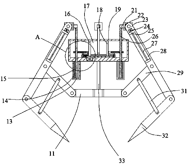
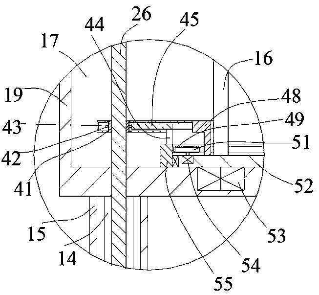
[0019] Such as Figure 1-Figure 2 As shown, the present invention will be described in detail. For the convenience of description, the orientations mentioned below are now specified as follows: figure 1 The projection relationship itself is in the same up, down, left, and right directions. The milling and clamping device of the present invention includes a matching box 19, which is provided with a transmission cavity 17, and the bottom of the matching box 19 is fixed. An intermediate fixed shaft 33 is provided. The lower end of the intermediate fixed shaft 33 is fixedly provided with a bottom plate 11, and a number of side swing rods 29 are arranged in the bottom plate 11 to rotate. The movable mating rod 25 is provided with a clamping mandrel 32 that rotates in the movable mating rod 25, and a connecting power rod 31 is pivoted between the clamping mandrel 32 and the side swing rod 29. The coupling A symmetrical externally threaded lifting rod 26 is slidably provided in the bo...


PUM


Abstract

The invention discloses a milling machining clamping device. The device comprises a matching box, wherein a transmission inner cavity is arranged in the matching box, a middle fixing shaft is fixedlyarranged on the lower end face of the matching box, the lower end face of the middle fixing shaft is fixedly provided with a bottom plate, the bottom plate is internally provided with a plurality of side swinging rods in a rotational mode, one sides of the side swinging rods are rotatably provided with movable matching rods, the movable matching rods are internally provided with clamping ejector rods in a rotational mode, and connecting power rods are rotatably arranged between the clamping ejector rods and the side swinging rods. The device is simple in structure, the device adopts the mode through which a clamping arm can be increased, so that the range in which a workpiece can be clamped by the device is expanded, the size range of a machined workpiece clamped by the device is expandedwhile clamping force of the device is improved, so that the efficiency and the working efficiency during milling machining are facilitated, and the clamping feeding and clamping machining are achieved.

Description

technical field [0001] The invention relates to the technical field of milling processing equipment, in particular to a milling processing clamping device. Background technique [0002] There are many shortcomings in the existing equipment. Due to the low effect of clamping the workpiece in the milling process, it greatly affects the milling accuracy of the workpiece in the milling process. In the process of continuous use, many problems are likely to occur. For example, because the clamping is not firm, the tool may accidentally touch the part when the equipment is milling, resulting in excessive feed and damage to the clamping mold, and the existing It is impossible to extend and improve the working range of the clamping when performing clamping work in the equipment, so that the technological range of the equipment is low, and in milling processing, there is no type of equipment that can realize the clamping of parts and equipment in the external space. Linkage, and it c...

Claims


Application Information

Patent Timeline
IPC IPC(8): B23Q3/00
CPCB23Q3/00
Inventor 胡月明
Owner 湖北宏胜机械有限公司
Why Eureka
Try Eureka