Candle Holder Mount

a candle and mounting bracket technology, applied in the field of candles, can solve the problems of affecting the manufacture of candles, affecting the use of candles, and affecting the use of candles, and achieve the effect of increasing the range of sizes of electric candles, easy and economical manufacturing, and reducing the risk of falling

Inactive Publication Date: 2012-12-27
STANZIONE MARY ANN
View PDF43 Cites 2 Cited by
  • Summary
  • Abstract
  • Description
  • Claims
  • Application Information

AI Technical Summary

Benefits of technology

[0010]It is another object of the present invention to prevent electric candles placed in the windows of various buildings from dislodging and falling.
[0011]It is yet another object of the present invention to increase the range of sizes of electric candles that may be deployed in window placements.
[0012]It is a still further object of the present invention to provide candle holder mounts having their own decorative form and function for permanent deployment on a variety of windowsills.
[0013]It is still another object of the present invention to provide a candle holder mount, as that term is used herein, which is easily and economically manufactured.
[0014]It is an even further object of the present invention to provide a candle holder mount which is capable of both permanent and temporary deployment.

Problems solved by technology

Unfortunately, the candles simulators are provided with electrical cords that extend downwardly in sufficient lengths to cause an unstable situation.
This causes a significant risk of falling, breaking of the bulb and a possible fire or at least some burn damage resulting from the exposure of the incandescent bulb filament.
In addition, even without cords, candles placed on windowsills are subject to being easily displaced, toppled and broken by activities such as dusting, or operation of the windows, drapes and blinds.
However, the batteries do not last long and have to be replaced multiple times in the course of even a short holiday display season.
Additionally, one is also left with a battery disposal problem.

Method used


Image

  • Candle Holder Mount
  • Candle Holder Mount
  • Candle Holder Mount

Examples


Embodiment Construction

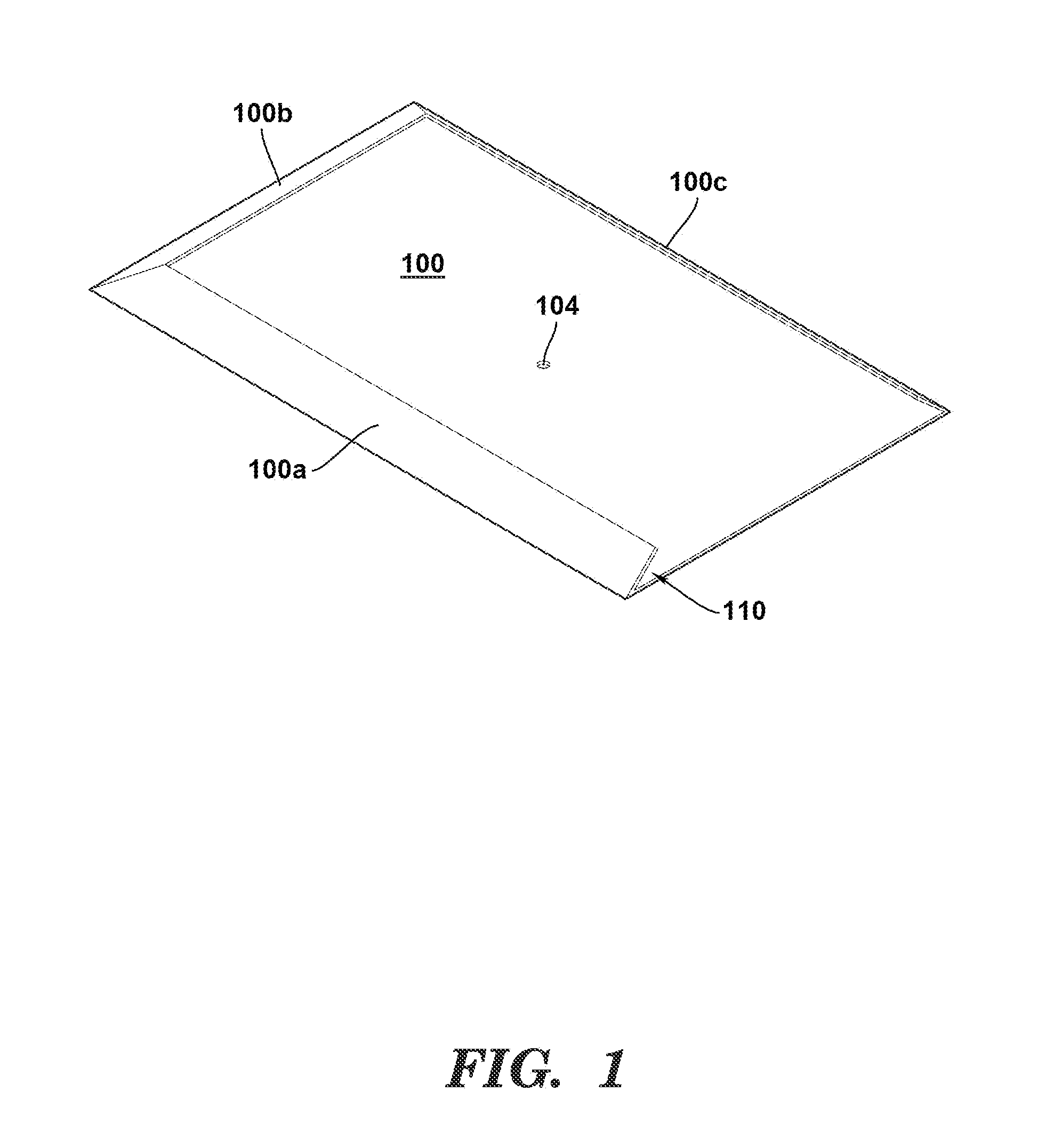
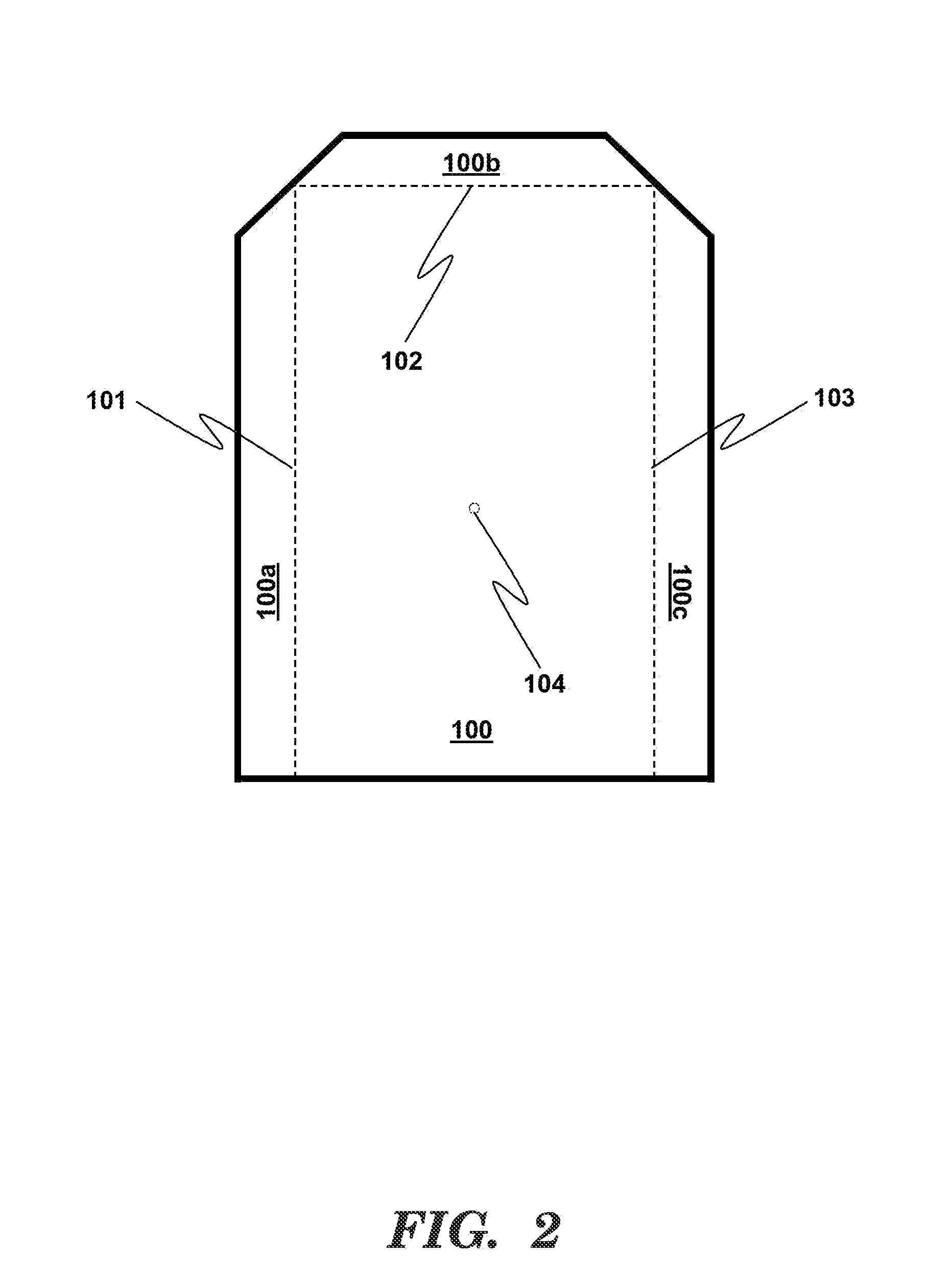
[0052]FIG. 1 shows one embodiment of the candle holder mount of the present invention. The mount has a flat base 100 with upwardly extending tabs 100a, 100b, and 100c disposed at acute angles to the base so that the interior surfaces of the tabs face downwardly toward the upwardly facing surface of the base. The tabs in this embodiment are disposed at the peripheral edges of the base, but may be disposed at locations other than the peripheral edge in other embodiments. The embodiment in FIG. 1 is has a quadrilateral base with three peripheral edge tabs and one edge that has no tab, thus forming an “open end.” That configuration creates a space 110 into which a bottom portion of a candle holder can enter the open end and be slid into the space defined by the base and tabs, as illustrated in FIG. 6. After the candle holder is assembled to the mount, the candle holder can be easily disassembled by sliding it out in the direction of the open end. The base provides greater stability than...


PUM

PropertyMeasurementUnit
tackaaaaaaaaaa
distanceaaaaaaaaaa
timeaaaaaaaaaa

Abstract

A candle holder mount is provided for holding electrical candle simulations firmly to a window sill of a home without the simulated candle being dragged off the sill by the weight of the electrical cord used to power the simulating device. The candle holder mount is affixable to window sills of various materials either in a permanent or removable fashion.

Description

TECHNICAL FIELD[0001]The present invention is generally directed to devices for holding candles, methods for manufacturing the device, and methods for using the device.BACKGROUND OF THE INVENTION[0002]The placement of candles in the windows of homes has been a longstanding tradition. In particular, the Christmas season has typically been a time for home decoration and the placement of candles in one or more windows as a decorative touch. In more recent history, with the use of various window treatments, the danger of fire posed by the use of wax candles, with their attendant flames, has led to the use of electrically simulated candles with decorative light bulbs having a shape intended to imitate the shape of a flame.[0003]These electrical candle simulations typically comprise a base portion and a cylindrical portion affixed to the top of the base portion. An electrical cord is disposed through the base portion so as to feed electrical wires to a standard socket mounted in the top p...

Claims


Application Information

Patent Timeline
Patent Type & Authority Applications(United States)
IPC IPC(8): F21V35/00B23P19/04
CPCF21V35/00F21S6/001F21V21/02F21V21/06Y10T29/49826F21V21/0824F21V21/0832F21W2121/004F21V21/0808
Inventor STANZIONE, MARY ANN
Owner STANZIONE MARY ANN
Why Eureka
Try Eureka