Pivoting push latch

Inactive Publication Date: 2007-05-31
ILLINOIS TOOL WORKS INC
View PDF14 Cites 26 Cited by
  • Summary
  • Abstract
  • Description
  • Claims
  • Application Information

AI Technical Summary

Benefits of technology

[0012] An advantage of the present invention is providing a push-push latch mechanism that operates easily and conveniently in a pivoting environment where the device to be latched moves in an arc about an axis.
[0013] Another advantage of the present invention is providing a push-push latch mechanism that operates smoothly and easily.
[0014] A further advantage of

Problems solved by technology

Some such push-push latch mechanisms have been relatively complex, with many component parts.
As a result, such mechanisms are expensive to manufacture, assemble and install.
While a sliding push-push latch as described above has achieved acceptance in some applications, in othe

Method used


Image

  • Pivoting push latch
  • Pivoting push latch
  • Pivoting push latch

Examples


Embodiment Construction

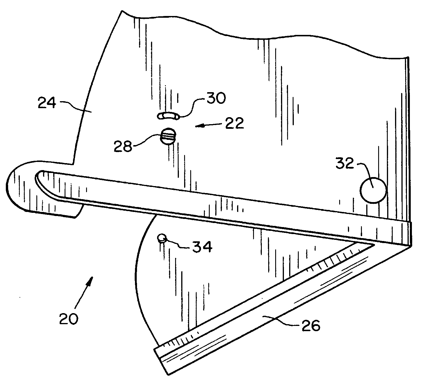
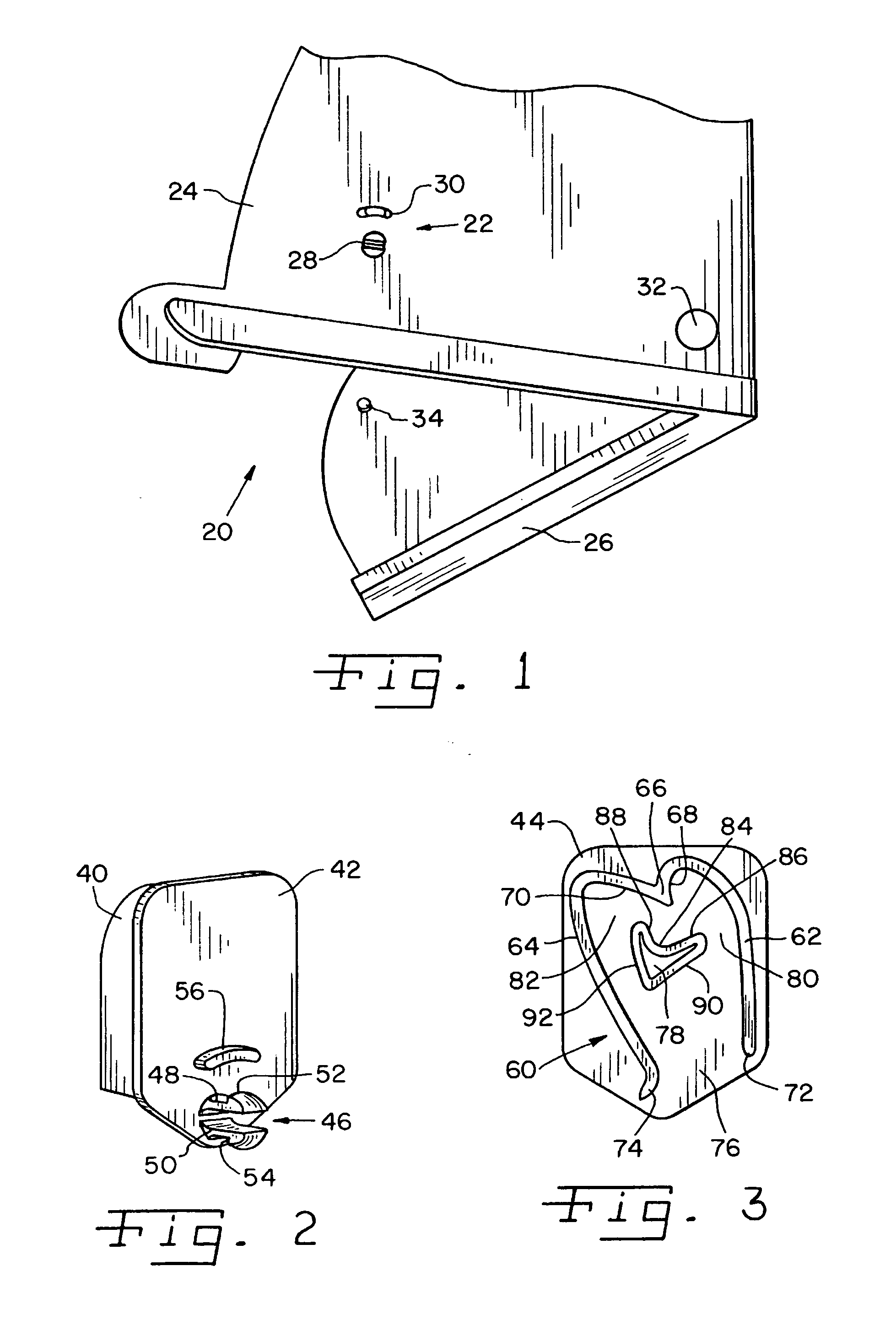
[0025] Referring now more specifically to the drawings and to FIG. 1 in particular, numeral 20 designates a latchable structure, which in the exemplary embodiment is a bin assembly, having a latch 22 in accordance with the present invention installed therein for securing the bin in a closed position. It should be understood that the exemplary illustration of bin 20 is merely for illustrative purposes, and the present invention can be used on a variety of objects and devices of different shape and for different purpose than bin 20. Generally, the present invention can be used for latching a structure having a first component and a second component movable relative to the first component.

[0026] Bin 20 includes a first component 24, which is a housing 24, and a second component 26, which is a door 26. Housing 24 is provided with a hole 28 and an arcuate slot 30 both for receiving latch 22, as will be described in greater detail hereinafter. Door 26 is pivotally connected to housing 24...


PUM


Abstract

A push-to-open and push-to-close latch mechanism for a latchable structure includes a protrusion movable in an arc and a push-push latch configuration that moves in an arc while opening and closing the structure.

Description

CROSS-REFERENCE TO RELATED APPLICATIONS [0001] The present regular United States Patent Application claims the benefits of U.S. Provisional Application Ser. No. 60 / 737,678, filed on Nov. 17, 2005.FIELD OF THE INVENTION [0002] The present invention relates generally to latch mechanisms and, more particularly, the invention pertains to latch mechanisms that are pushed to open and pushed to close. BACKGROUND OF THE INVENTION [0003] Latch mechanisms that are pushed to open and pushed to close are used extensively in many constructions and assemblies and have received broad acceptance in the automotive industry. So called “push-push latches” are known for use on container holders, storage compartments, ashtrays, sunglass bins and other compartments within automobiles. Such mechanisms are used also in the electronics industry for stereos, televisions, video devices and the like which have compartments and things for which it is convenient and / or desirable to use a pushing motion for both ...

Claims


Application Information

Patent Timeline
IPC IPC(8): E05C19/00
CPCE05C19/022Y10T292/42
Inventor BELLA, JOSEPH J.
Owner ILLINOIS TOOL WORKS INC
Why Eureka
Try Eureka