Aggregate firmness testing device and method
A test device and a solid technology, applied in the field of aggregate testing, can solve problems such as time-consuming, labor-intensive, potential safety hazards, and low efficiency, and achieve the effects of convenient and smooth operation, avoiding track deviation, and improving stability
Inactive Publication Date: 2020-08-14
JSTI GRP INSPECTION & CERTIFICATION CO LTD +1
View PDF5 Cites 0 Cited by
- Summary
- Abstract
- Description
- Claims
- Application Information
AI Technical Summary
Problems solved by technology
[0004] 1. In the existing test process, the total time spent on the multiple cycles of immersion and drying of aggregates reaches 1 to 2 days. Due to the lack of effective automatic operation and monitoring systems, manual continuous observation and manipulation are usually required , not only time-consuming and labor-intensive, but also inefficient;
[0005] 2. For the same typ
Method used
View moreImage
Smart ImageViewing Examples
Examples
 PUM
 Abstract
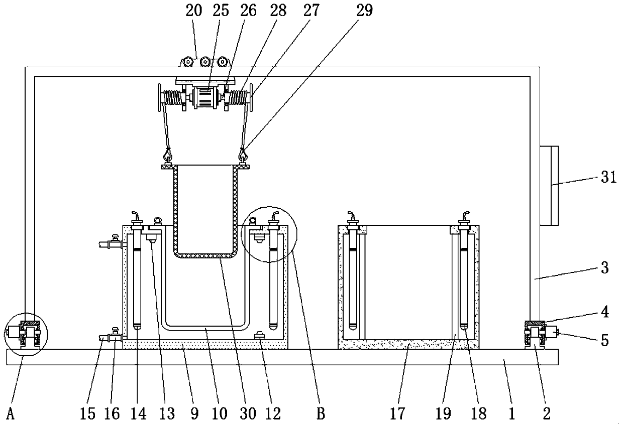
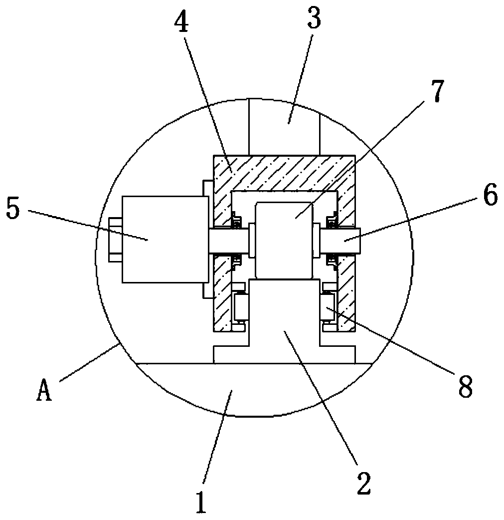
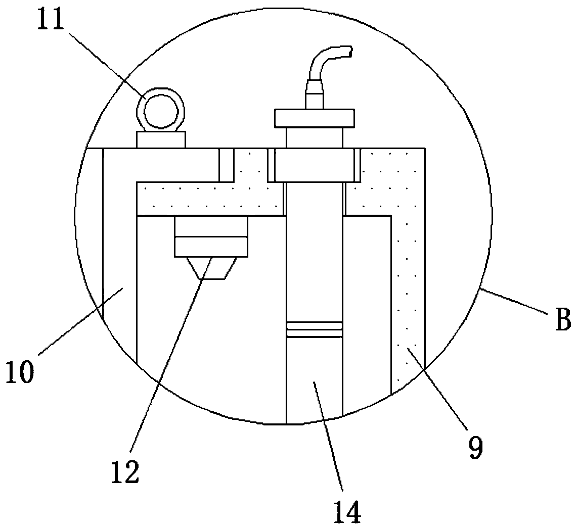
The invention relates to the technical field of aggregate tests, and particularly relates to an aggregate firmness testing device and method. The device comprises a workbench, a portal frame, a waterbath box, a drying box and a net barrel, wherein the water bath box is fixed to the left side of the top end of the workbench, an upper temperature sensor and a lower temperature sensor are fixed on the right side in the water bath box, first electric heating tubes are inserted into the left side and the right side in the water bath box, the drying box is fixed to the right side of the top end ofthe workbench, cross beams are welded to the left lower end and the right lower end of the portal frame, X-direction motors are fixed to the centers of one sides of the cross beams, a Y-direction motor is fixed to the center of one side of a movable frame, and a Z-direction motor is fixed to the bottom end of the movable frame. Full-automatic operation of the aggregate firmness test is realized, the overall operation is convenient and smooth, the stability in the aggregate firmness testing process is improved, and the positioning, dismounting and mounting are also facilitated, so that the later maintenance difficulty is reduced.
Description
technical field [0001] The invention relates to the technical field of aggregate testing, in particular to an aggregate firmness testing device and testing method. Background technique [0002] Aggregate solidity test is one of the requirements of JTG E42-2005 Highway Engineering Aggregate Test Regulations, and it is an important index to describe the frost resistance of aggregates. The content of the test is to pass the aggregate (including coarse aggregate-gravel, fine aggregate-sand, etc.) through saturated sodium sulfate (Na 2 SO 4 ) solution for repeated immersion and drying, and the test of not causing significant damage or strength reduction while bearing the sodium sulfate crystallization pressure is the most commonly used test method for evaluating the firmness of aggregates. [0003] However, there are still some problems in the existing aggregate firmness test device and test method, and the specific problems are as follows: [0004] 1. In the existing test pro...
Claims
Login to View More Application Information
Patent Timeline
 IPC IPC(8): G01N5/04G01N1/30G01N1/34G01N1/44
CPCG01N1/30G01N1/34G01N1/44G01N5/04
Inventor 李世豪罗东志何新原巩士范张飞龙
Owner JSTI GRP INSPECTION & CERTIFICATION CO LTD
Features
- R&D
- Intellectual Property
- Life Sciences
- Materials
- Tech Scout
- Unparalleled Data Quality
- Higher Quality Content
- 60% Fewer Hallucinations
Learn More Browse by: Latest US Patents, China's latest patents, Technical Efficacy Thesaurus, Application Domain, Technology Topic, Popular Technical Reports.
© 2025 PatSnap. All rights reserved.Legal|Privacy policy|Modern Slavery Act Transparency Statement|Sitemap|About US| Contact US: help@patsnap.com


