Magnetic head device

a magnetic head and slider technology, applied in the direction of maintaining the head carrier alignment, recording information storage, instruments, etc., can solve the problems of excessive decrease of the flying height of the rear dynamic-pressure-generating part, and affecting the stability of the magnetic head device. , to achieve the effect of reducing the “side positive pressure reduction, reducing the attractive force, and reducing the flying heigh

Inactive Publication Date: 2007-05-31
TDK CORPARATION
View PDF13 Cites 19 Cited by
  • Summary
  • Abstract
  • Description
  • Claims
  • Application Information

AI Technical Summary

Benefits of technology

[0014] The present embodiments may obviate one or more of the drawbacks of the related art. For example, in one embodiment, a magnetic head device is capable of achieving a low flying height of a magnetic functional unit from a recording medium, and also stabilizes the flying position (pitch angle) of a slider and reduces variations in flying height when air density in the use environment changes.

Problems solved by technology

As the flying height of a slider in a magnetic head device has decreased recently, variations in flying height caused by changes in air density are becoming a problem.
However, since this magnetic head device has a structure in which a negative pressure is created mainly in the rear dynamic-pressure-generating part, a decrease in air density in the use environment may lead to an excessive decrease in the flying height of the rear dynamic-pressure-generating part.
However, since a balance between a negative pressure created on the negative-pressure-generating part in the middle section and a negative pressure created on the rear dynamic-pressure-generating part is not adjusted, the negative-pressure-generating part in the middle section may cause an excessive decrease in the flying height of the magnetic head when air density in the use environment decreases.
Since the negative-pressure-generating area is located in the middle area where air is received when the magnetic head device is in the tilt position, a decrease in air density reduces attractive force in the negative-pressure-generating area.

Method used


Image

  • Magnetic head device
  • Magnetic head device
  • Magnetic head device

Examples


Embodiment Construction

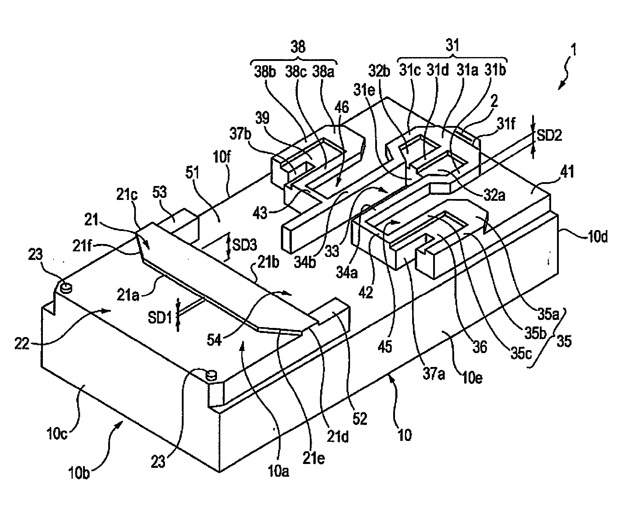
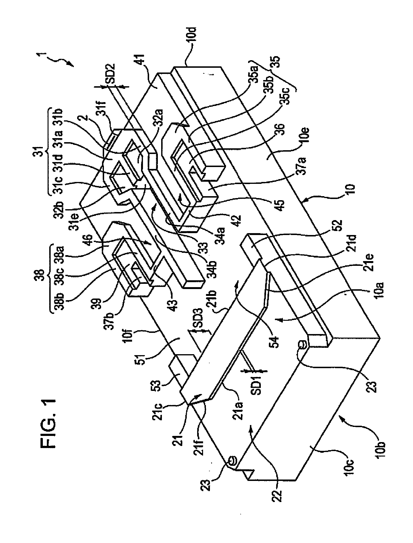
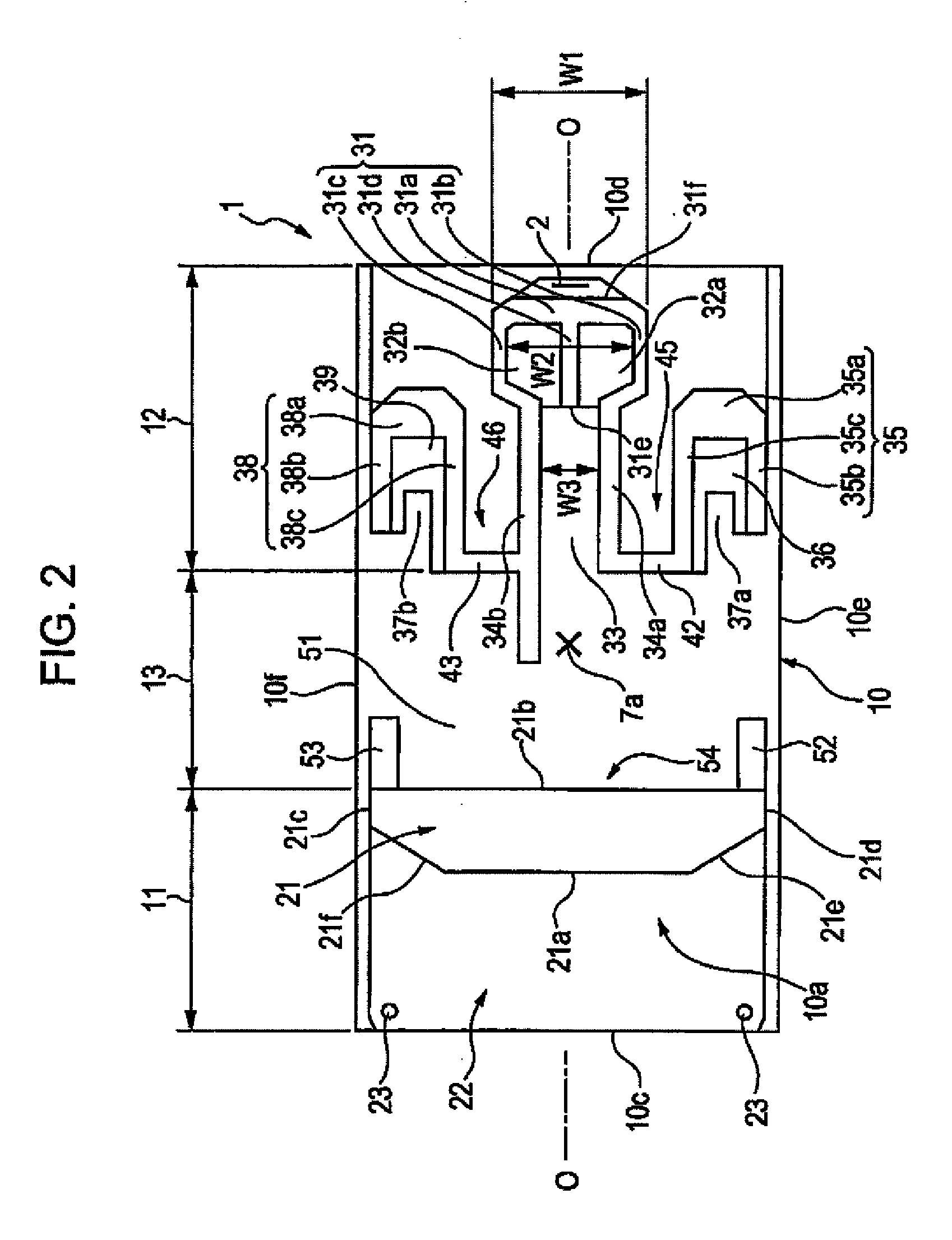
[0047] In one embodiment, as shown in FIG. 1 and FIG. 2, a magnetic head device 1 includes a cubic-shaped slider 10 made of alumina titanium carbide (Al2O3—TiC) or the like and a magnetic functional unit 2 mounted on the slider 10.

[0048] The magnetic functional unit 2 includes a reading functional part configured to read magnetic signals recorded in a recording medium D using an MR effect, a GMR effect, or a tunnel magnetoresistive (TMR) effect, and a recording functional part that is composed of a yoke of magnetic material and a coil of conductive material, which are fabricated by thin film processing, and configured to write magnetic signals to the recording medium D.

[0049] The slider 10 has a facing side 10a that faces the recording medium D, and a pressing side 10b that faces opposite the facing side 10a. The slider 10 has a leading end surface 10c facing toward the direction from which airflow generated over the recording medium D comes, and a trailing end surface 10d from wh...


PUM

PropertyMeasurementUnit
depthaaaaaaaaaa
depthaaaaaaaaaa
depthaaaaaaaaaa

Abstract

A slider of a magnetic head device has a side that faces a recording medium and on which a first positive pressure is exerted on the leading side and a second positive pressure is exerted on the trailing side. In the area between the first positive pressure area and the second positive pressure area, a small second negative pressure is created at the front, a first negative pressure larger than the second negative pressure is created at the rear, and a third positive pressure is exerted on both sides of the first negative pressure area. When air density decreases, the small second negative pressure in a middle area and the large first negative pressure at the rear of the second negative pressure area stabilize the pitch angle of the slider and prevent an excessive decrease in the flying distance of a trailing end portion.

Description

[0001] This patent document claims the benefit of Japanese Patent Application No. 2005-335605 filed Nov. 21, 2005, which is hereby incorporated by reference. BACKGROUND [0002] 1. Field [0003] The present embodiments relate to a magnetic head device. [0004] 2. Related Art [0005] Generally, a magnetic head device that includes a slider facing a magnetic recording medium and is provided with a magnetic functional unit on a trailing end thereof is used for reading a magnetic signal from and writing a magnetic signal to a magnetic recording medium, such as a hard disk. The magnetic functional unit includes a reproducing functional part using a magnetoresistive (MR) effect or a giant magnetoresistive (GMR) effect, and a recording functional part composed of a yoke, a coil, and the like that are made of magnetic material and formed of thin films. [0006] The slider of the magnetic head device is pressed against a surface of the magnetic recording medium by an elastic member that is referred...

Claims


Application Information

Patent Timeline
Patent Type & Authority Applications(United States)
IPC IPC(8): G11B19/02
CPCG11B5/6005F15B15/22F15B2211/7051F15B2211/755
Inventor KONDO, YASUYUKIUEDA, JUNSEIUEDA, SHOUHEIUEDA, MIHOKOISHIHARA, HIROHISA
Owner TDK CORPARATION
Why Eureka
Try Eureka