

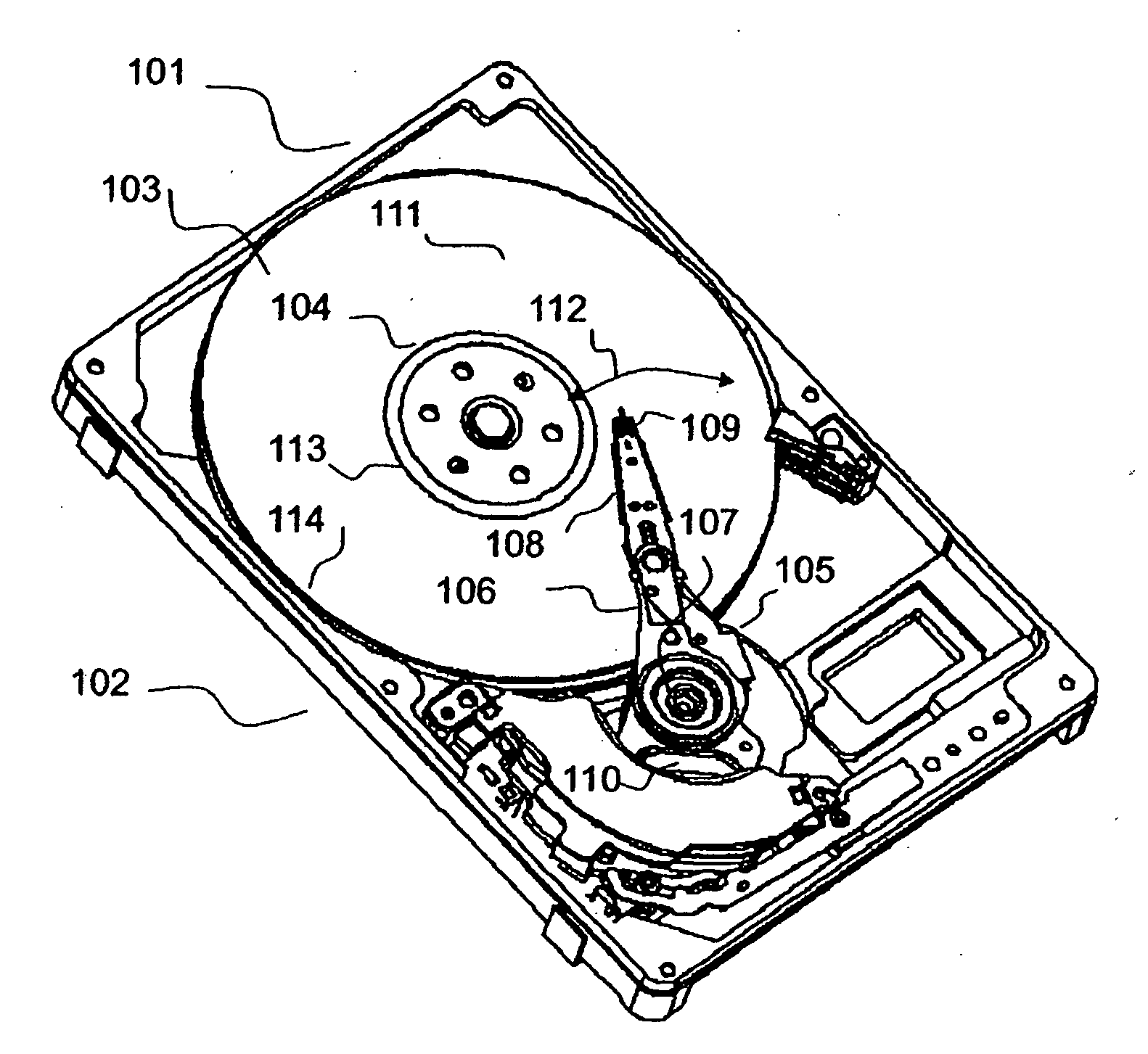
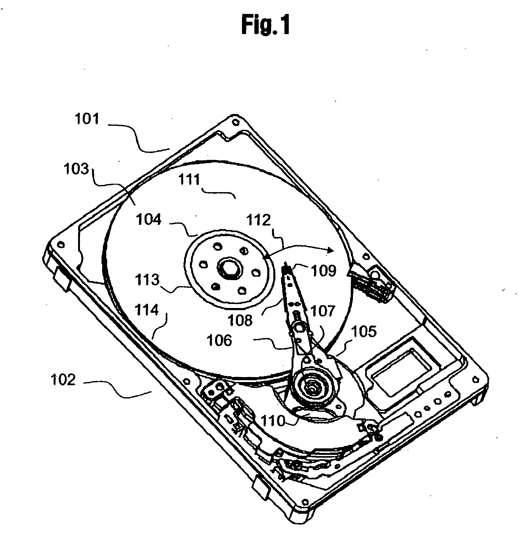
Disk drive and head slider
a disk drive and slider technology, applied in the direction of maintaining the head carrier alignment, recording information storage, instruments, etc., can solve the problems of data irreparably lost, read/write error, read/write error, etc., to reduce the accumulation of lubricant, improve the reliability of the disk drive, and reduce the height of the flying obj
- Summary
- Abstract
- Description
- Claims
- Application Information
AI Technical Summary
Benefits of technology
Problems solved by technology
Method used
Image

Examples
first embodiment
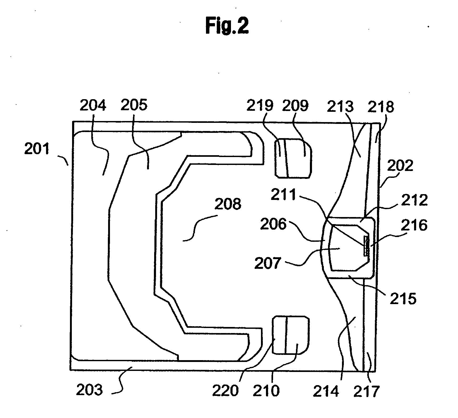
[0038]FIG. 2 shows an exemplary perspective diagram of an example of a magnetic head slider of a FIG. 3(A) shows an exemplary perspective diagram of FIG. 2, and FIG. 3B shows a perspective diagram of an outflow end portion of the magnetic head slider shown in FIG. 2.
[0039]The magnetic head slider of the first embodiment has an air inflow end 201, air outflow end 202, and air bearing surface 203. The air bearing surface 203 has an inflow side step (shallow groove) surface 204, an inflow side rail 205 having an inflow side rail surface, an outflow side rail 207 having an outflow side rail surface and a conversion element 211, an outflow side step surface 206, a negative pressure groove 208, side rails 209 and 210, each side rail forming an air bearing surface of a head slider side face, side step surfaces 219 and 220 provided at outflow end sides of respective side rails, and flow pads 213 and 214 provided over full width of the head slider.
[0040]A surface of the inflow side rail 205...
second embodiment
[0061]FIG. 10 shows an exemplary plane diagram of a head slider of a The head slider of the embodiment has an air inflow end 201, air outflow end 202, and air-bearing surface 203. The air-bearing surface 203 has an inflow-side step bearing surface 204, an inflow side rail 205, and a conversion element 211, and further has an U-shaped outflow side rail 1001, an outflow-side step bearing surface 206, a negative pressure groove 208, side rails 209 and 210, side step surfaces 219 and 220, and flow pads 213 and 214. The U-shaped outflow side rail 1001 increases attenuation of velocity, so that decreases velocity dependence of flying amount. The flow pads 213, 214 and an outflow end 1002 suppress a backflow from a portion near the outflow end compared with a write / read element. In FIG. 10, a stepped portion of the outflow end 1002 near the outflow end compared with the conversion element 211 is omitted on the drawing.
third embodiment
[0062]FIG. 11 shows an exemplary plane diagram of a head slider of a The head slider of the embodiment has an air inflow end 201, air outflow end 202, and air-bearing surface 203. The air-bearing surface 203 has an inflow-side step bearing surface 204, an inflow side rail 205, and a conversion element 211, and further has an U-shaped outflow side rail 1001, an outflow-side step bearing surface 206, a negative pressure groove 208, side rails 209 and 210, side step bearing surfaces 219 and 220, and flow pads 213 and 214, wherein an outflow end 1002 near an outflow end compared with a write / read element has no stepped portion. The flow pads 213 and 214 have grooves 1101 and 1102 respectively. The grooves 1101 and 1102 change a configuration of flow on the flow pads 213 and 214 so as to increase critical depth on the flow pads 213 and 214 respectively. Again in FIG. 11, a stepped portion of the outflow end 1002 near the outflow end compared with the conversion element 211 is omitted on...
PUM
| Property | Measurement | Unit |
|---|---|---|
| depth | aaaaa | aaaaa |
| depth | aaaaa | aaaaa |
| velocity | aaaaa | aaaaa |
Abstract
Description
Claims
Application Information