Magnetic head driving circuit and magnetic disk device

a driving circuit and magnetic disk technology, applied in the direction of magnetic recording, data recording, instruments, etc., can solve the problem of likely error

Active Publication Date: 2007-05-22
TDK CORPARATION
View PDF9 Cites 4 Cited by
  • Summary
  • Abstract
  • Description
  • Claims
  • Application Information

AI Technical Summary

Benefits of technology

[0022]An object of the present invention is to provide a magnetic head driving circuit and a magnetic disk device which achieve a low flying-height with thermal protrusion and thus a reliable write operation on the magnetic disk.
[0026]In the present invention, the frequency f2 of the signal in the preamble portion is higher than half the frequency f1 of the signal in the user data portion. Thus, in the forefront portion immediately after the start of write operation, heat generation is accelerated by the high frequency of the write current in the preamble portion. Consequently, sufficient thermal protrusion is achieved until the beginning of the user data portion. This ensures a low flying-height and resultant high write characteristic in the write operation.
[0028]In another aspect of magnetic head driving circuit according to the present invention, the frequency f2 of the signal in the preamble portion may include a harmonic f3 of the frequency that is half the frequency f1 of the signal in the user data portion, the harmonic f3 being superimposed on the frequency f2 . In this case, the magnetic head driving circuit receives a write data signal and a clock signal. The inputted clock signal, which is at a frequency of the harmonic f3, is combined with the write data signal to form a write current, and the write current is outputted. The frequency f2 of the signal in the preamble portion may be the same as half the frequency f1 in the signal in the user data portion. This aspect of magnetic head driving circuit provides effects similar to those of the previously-described aspect.

Problems solved by technology

Thus, errors have been likely to happen.

Method used


Image

  • Magnetic head driving circuit and magnetic disk device
  • Magnetic head driving circuit and magnetic disk device
  • Magnetic head driving circuit and magnetic disk device

Examples


first embodiment

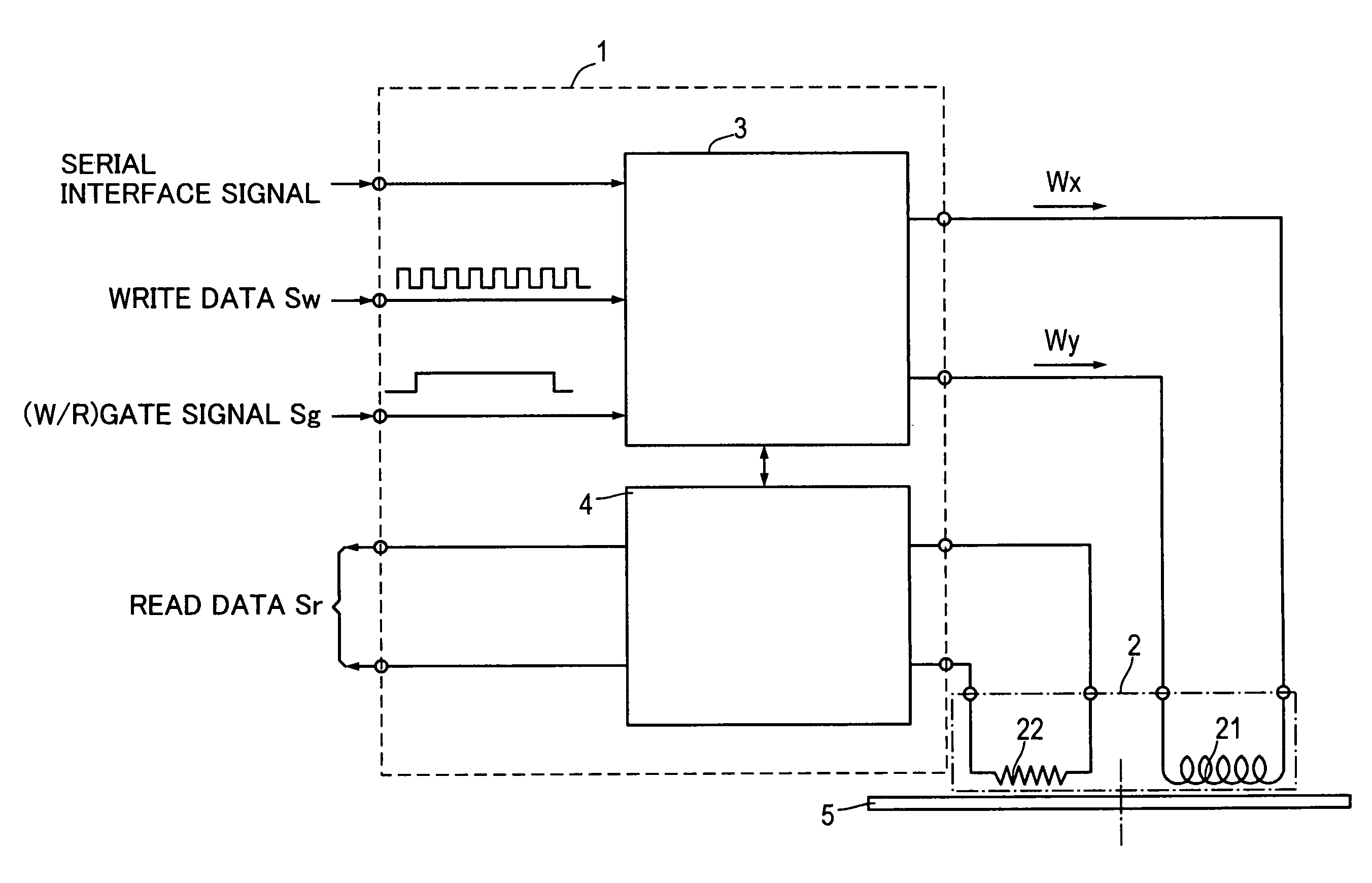
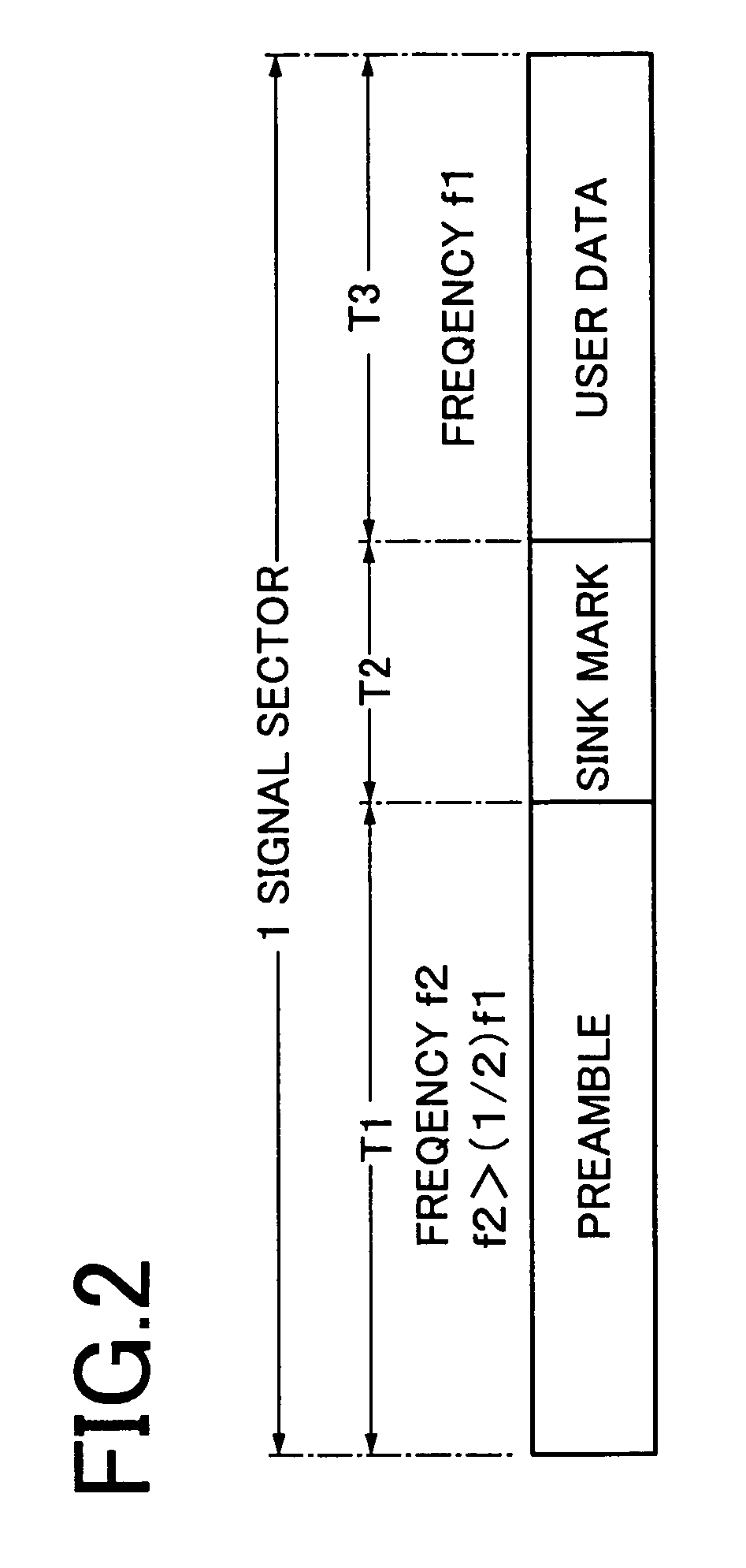
[0047]FIG. 1 shows a magnetic disk device having a magnetic head driving circuit according to the present invention, and FIG. 2 shows the configuration of a basic single sector. First, referring to FIG. 1, a magnetic head driving circuit 1 comprises a write circuit 3 and a read circuit 4, and is combined with a magnetic head 2 and a magnetic disk 5 to form a magnetic disk device.

[0048]The magnetic head 2 provides the magnetic disk 5 with magnetic recording by means of the action of a write current Iw generated by write voltages Wx and Wy supplied from the magnetic head driving circuit 1.

[0049]The magnetic head 2 has a write element 21 and a read element 22. The write element 21 is generally formed out of an induction-type electromagnetic conversion element, and the read element 22 is formed out of a giant magnetoresistance effect element (hereinafter, referred to as GMR) such as a spin valve film (hereinafter, referred to as a SV film) or a ferromagnetic tunnel junction element (her...

second embodiment

[0070]FIG. 8 shows the configuration of a magnetic disk device having a magnetic head driving circuit according to the present invention. In FIG. 8, in comparison with the embodiment shown in FIG. 1, a clock signal Sc and a (P / D) gate signal Sg2 have been added as signals to be inputted to a write circuit 3.

[0071]FIG. 9 shows waveforms in the preamble portion in the second embodiment. The fundamental frequency f2 of the write data signal in the preamble portion T1 is 200 MHz, which is half the frequency f1 (400 MHz) of the signal in the user data portion T3.

[0072]The write current Iw shown in FIG. 9(E) is obtained as a result in that, for example, the harmonic f3 of the frequency that is half the frequency f1 of the signal in the user data portion T3 is superimposed on the frequency f2 that is a fundamental frequency of the write data signal in the preamble portion T1, when the (P / D) gate signal Sg2 is in a LOW state and the clock signal Sc is in a DOWN state as shown in FIG. 9.

[007...


PUM

PropertyMeasurementUnit
heightaaaaaaaaaa
frequency f1aaaaaaaaaa
frequency f2aaaaaaaaaa

Abstract

The invention is directed to a magnetic head driving circuit and a magnetic disk device which achieve a low flying-height with thermal protrusion and thus a reliable write operation on the magnetic disk. The write circuit 3 receives the write data signal Sw inputted therein, and generates and outputs the write voltages Wx, Wy based upon the inputted signal. The write voltages Wx, Wy are composed of a preamble portion T1, a sink mark T2 and a user data portion T3 in each sector for magnetic recording. In the write voltage, the frequency f2 of the signal in the preamble portion T1 is higher than half the frequency f1 of the signal in the user data portion T3.

Description

TECHNICAL FIELD[0001]The present invention relates to a magnetic head driving circuit and a magnetic disk device. More particularly, the invention relates to the improvement in a magnetic head driving circuit.BACKGROUND OF THE INVENTION[0002]A flying thin-film magnetic head is ordinarily provided with a write element (an induction-type electromagnetic conversion element) and a read element at the air flowing-out end of the slider. The induction-type electromagnetic conversion element is covered with a protective film. The protective film, which is made of an inorganic insulating material such as alumina, forms the most outside layer at the air flowing-out end.[0003]The induction-type electromagnetic conversion element comprises first and second magnetic films, a gap film, a coil film, an insulating film and the like. In the first and second magnetic films, the end portions at the air bearing surface (hereinafter, referred to as ABS) of the slider face each other over a gap film, so ...

Claims


Application Information

Patent Timeline
Patent Type & Authority Patents(United States)
IPC IPC(8): G11B5/09G11B21/02G11B5/02
CPCG11B5/012G11B5/09G11B5/607
Inventor OTSUKI, MITSUOKIYONO, HIROSHINISHIO, NOBUTAKAMATSUKUMA, HIROKI
Owner TDK CORPARATION
Why Eureka
Try Eureka