
Ultra-low flying height slider design

a slider and ultra-low technology, applied in the direction of maintaining head carrier alignment, recording information storage, instruments, etc., can solve the problems of unintended contact between the slider assembly and the magnetic rotating disk, loss of recorded data, and affecting the resolution and data transfer capabilities of the accompanying transducer or read/write element, etc., to achieve ultra-low and constant flying height, control the crown sensitivity of the slider, and control the camber sensitivity

Inactive Publication Date: 2005-01-13
SAE MAGNETICS (HK) LTD
View PDF7 Cites 5 Cited by
  • Summary
  • Abstract
  • Description
  • Claims
  • Application Information

AI Technical Summary

Benefits of technology

[0014] The present invention provides a subambient pressure air bearing slider with a plurality of air bearing surfaces (ABSs) that provide an ultra-low and constant flying height even in varying temperature environments. The design may be referred to as “modular” in that individual parameters for the slider, such as crown, camber, and sub-ambient pressure, may be separately controlled through the dimensions and placement of the various components of the slider. In other words, controlling one of these parameters may be effectively “decoupled” from other affecting others of these parameters. For example, crown sensitivity of the slider may be controlled by controlling the length and placement of side ABS structures in addition to altering the dimensions of a trailing ABS. Camber sensitivity may be controlled by setting the width of the side ABS structures. Finally, once camber and crown sensitivity for the slider are set, overall flying height for the slider may be set by appropriate placement of low-profile members creating a sub-ambient pressure region between them, resulting in a lower flying height for the slider.

Problems solved by technology

Fluctuations in flying height are known to adversely affect the resolution and the data transfer capabilities of the accompanying transducer or read / write element.
Additionally, changes in flying height may result in unintended contact between the slider assembly and the magnetic rotating disk.
The deterioration or wear of the recording media may lead to the loss of recorded data, while slider wear may also result in the ultimate failure of the transducer or magnetic element.
What often causes changes to the flying height is the continual high speed movement of the slider across the rotating disk while performing read or write operations.
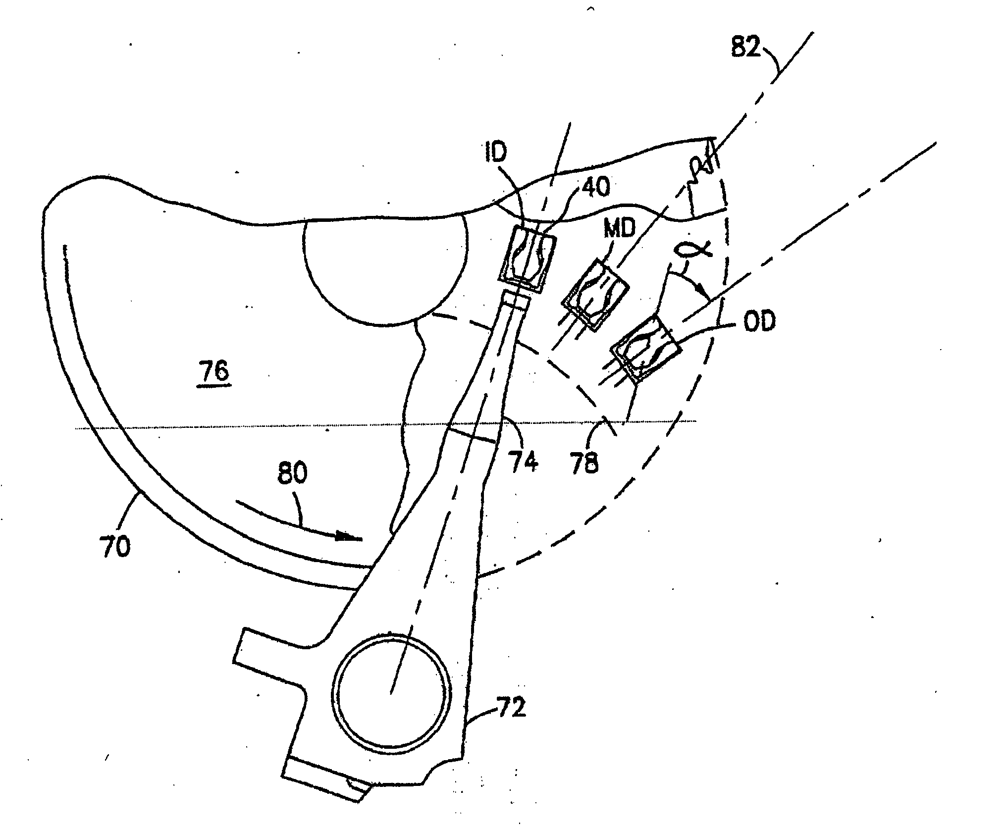
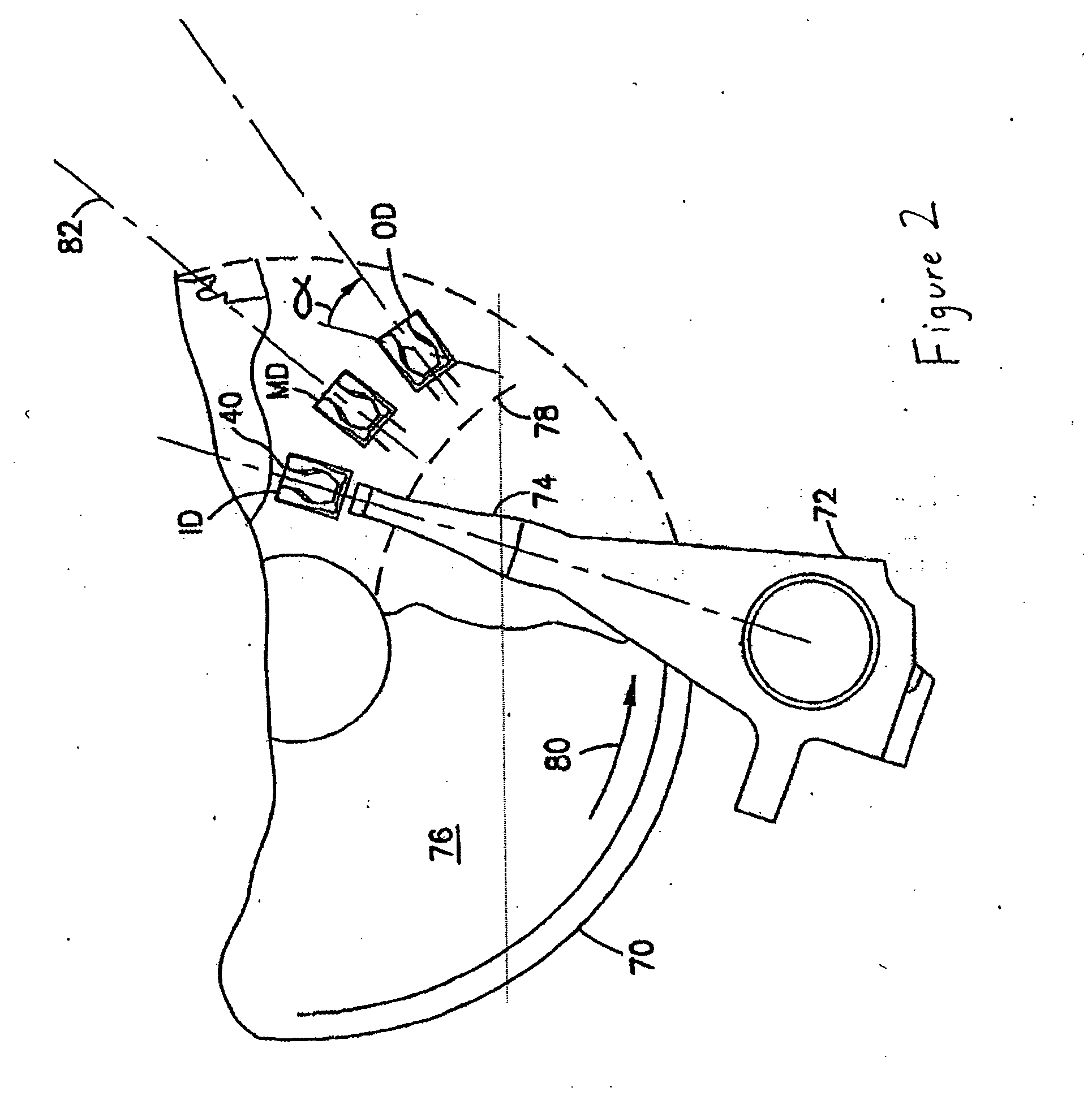
The flying height of a slider is also adversely affected by changes in skew.
It has often been observed that at skew values above zero, sliders are pressurized at reduced values which cause an undesirable decrease in flying height.
Even a relatively moderate skew angle range adversely affects the flying capabilities of a slider.
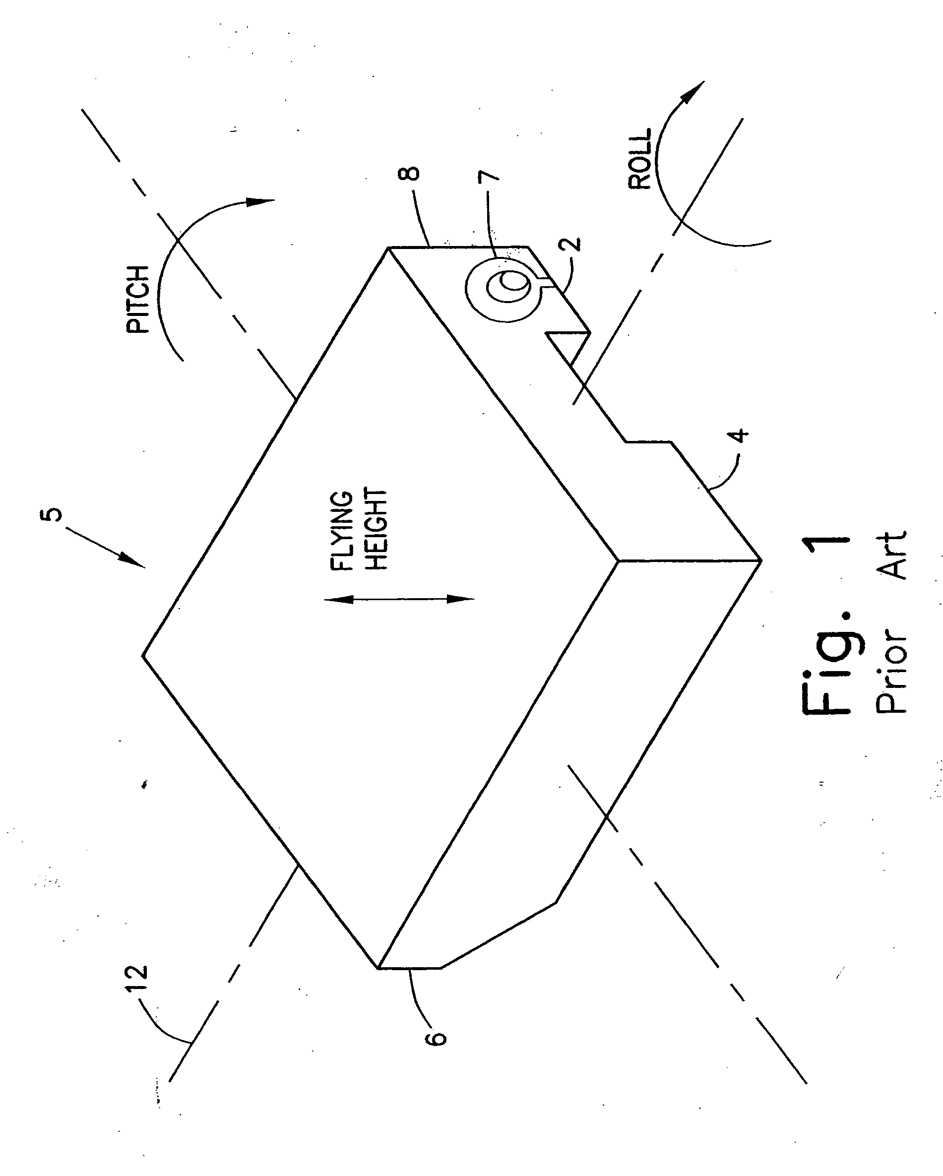
This imbalance causes slider roll where one side of the slider body is closer to the disk surface than the other side.
Although catamaran sliders are initially effective in providing an adequate flying height, they are especially sensitive to varying skew angle ranges and other adverse flying conditions.
When the skew angle is increased, such as when the flying slider moves across the rotating disk, the air pressure distribution beneath the rails may become distorted.
As a result, the slider experiences an uneven distribution of pressure which may cause the slider to roll in one direction such that the flying height is not uniform between the ABS rails.
The mounted transducer may therefore be unable to operate effectively or accurately perform its data transfer operations.
This counteraction of negative and positive forces has been known to increase the stability and air bearing stiffness of the slider, provide rapid slider take-off, and reduce its sensitivity to variations in conditions such as changing disk velocity and radial movement which cause fluctuations in flying height.
However, the offsetting forces created in a subambient pressurization scheme may often present undesirable effects that actually cause variations in flying height.
Different degrees of effectiveness are provided by these ABS designs which overall do not control flying height, or pitch and roll angles very well.
These configurations also typically fail to control the increase in slider pitch angle when moving from inner track to the outer track regions.
As described above, one problem seen with lower flying heights is that there is more of a risk for head / disk contact, which can cause damage to the slider head and / or the magnetic recording disk.

Method used


Image

  • Ultra-low flying height slider design
  • Ultra-low flying height slider design
  • Ultra-low flying height slider design

Examples


Embodiment Construction

[0021]FIG. 3 is a plan view of the bottom side of a slider 10 for a subambient pressure slider in accordance with an embodiment of the present invention. It will be understood that for purposes of describing particular features of an ABS as follows, the entire slider body, which may be formed from a substrate material such as Al2O3TiC, is not shown. The slider 10 illustrated in FIG. 3 includes a leading air bearing surface 12. Air bearing surface is set off from a leading edge 13 of the slider 10 by a leading step 14. In this embodiment, the leading step 14 has a depth relative to the leading air bearing surface 12. In this embodiment the depth is between 2 and 10 microinches. Two side air bearing surfaces 15, 16 are provided at the inner and outer edges of the slider 10. Though two such surfaces are provided, the present invention is not limited to this number. Each of the air bearing surfaces 15, 16 includes a secondary structure 15a, 16b, respectively that is at a lower height. I...


PUM


Abstract

A subambient pressure air bearing slider for disk drives and the like is presented where features of the slider are modular, in that certain parameters of the slider can be modified independently of one another. In one example, lateral dimensions and placement of side and trailing air bearing surfaces can be used to control flying height sensitivity due to crowning in the slider. Longitudinal dimensions of the side air bearing surfaces can be used to control flying height sensitivity due to camber in the slider body. Low-profile members (e.g., ones that do not form air bearing surfaces) may be used to control the dimensions of the subambient pressure region to control overall flying height.

Description

FIELD OF THE INVENTION [0001] The present invention is directed to air bearing slider designs in disk drives. More particularly, the present invention pertains to a modular design for an air bearing surfaces of a slider to achieve an ultra-low flying height. BACKGROUND OF THE INVENTION [0002] Hard disk drives are common information storage devices essentially consisting of a series of rotatable disks that are accessed by magnetic reading and writing elements. These data transferring elements, commonly known as transducers, are typically carried by and embedded in a slider body that is held in a close relative position over discrete data tracks formed on a disk to permit a read or write operation to be carried out. In order to properly position the transducer with respect to the disk surface, an air bearing surface (ABS) formed on the slider body experiences a fluid air flow that provides sufficient lift force to “fly” the slider and transducer above the disk data tracks. The high sp...

Claims


Application Information

Patent Timeline
IPC IPC(8): G11B5/60G06F15/173G11B21/21
CPCG11B5/6005G11B5/6082G11B21/21
Inventor CHA, ELLIS T.
Owner SAE MAGNETICS (HK) LTD
Learn More