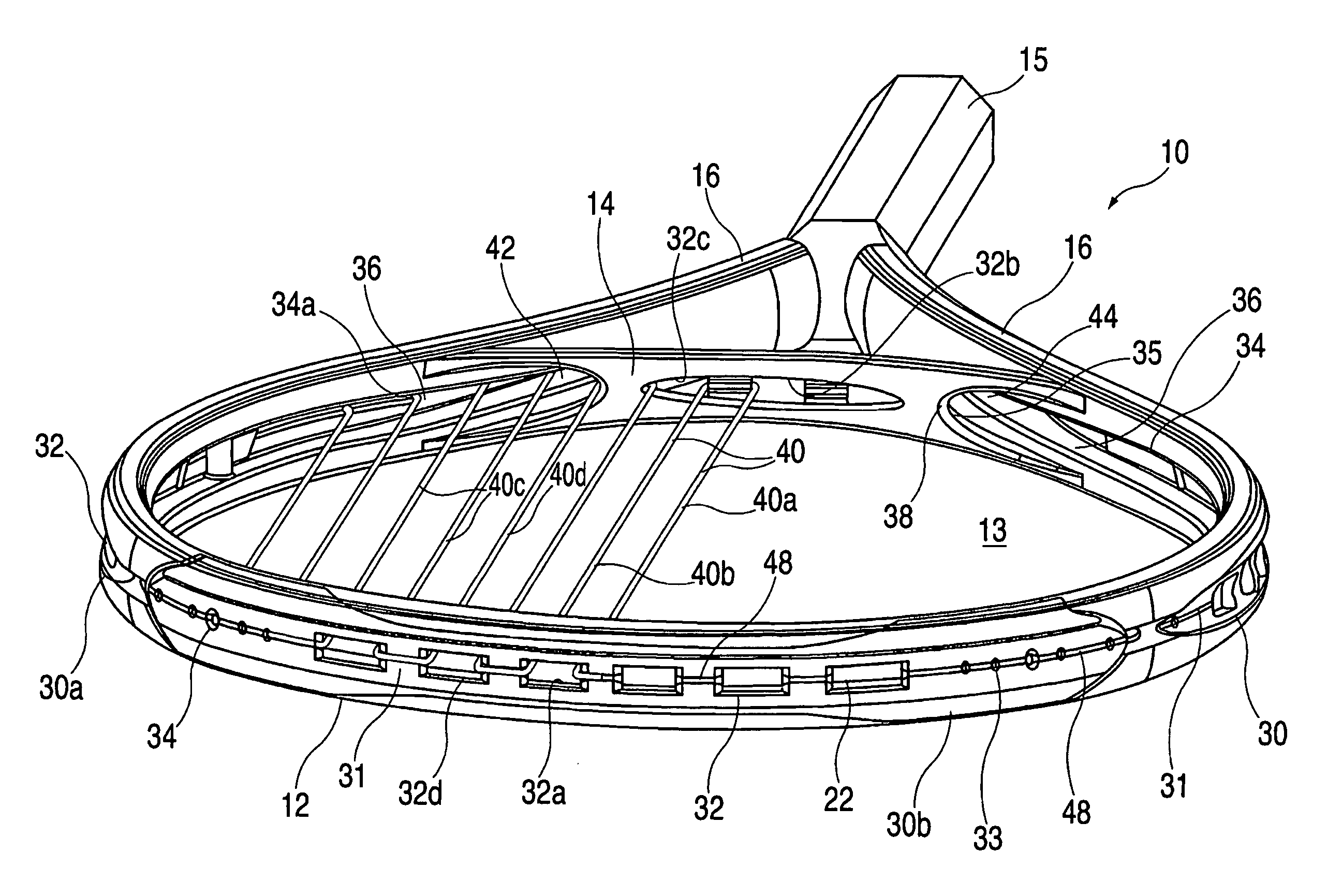
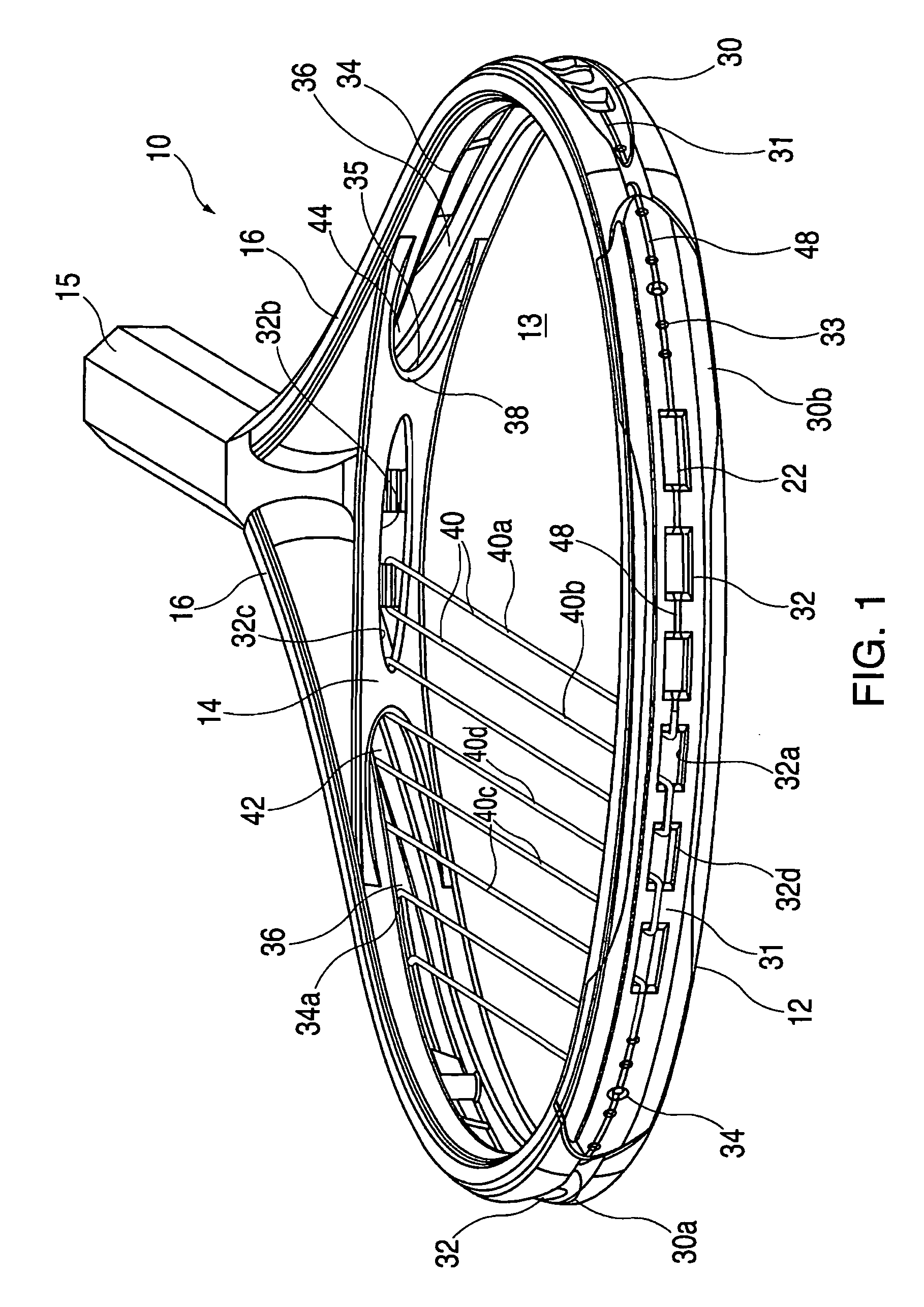
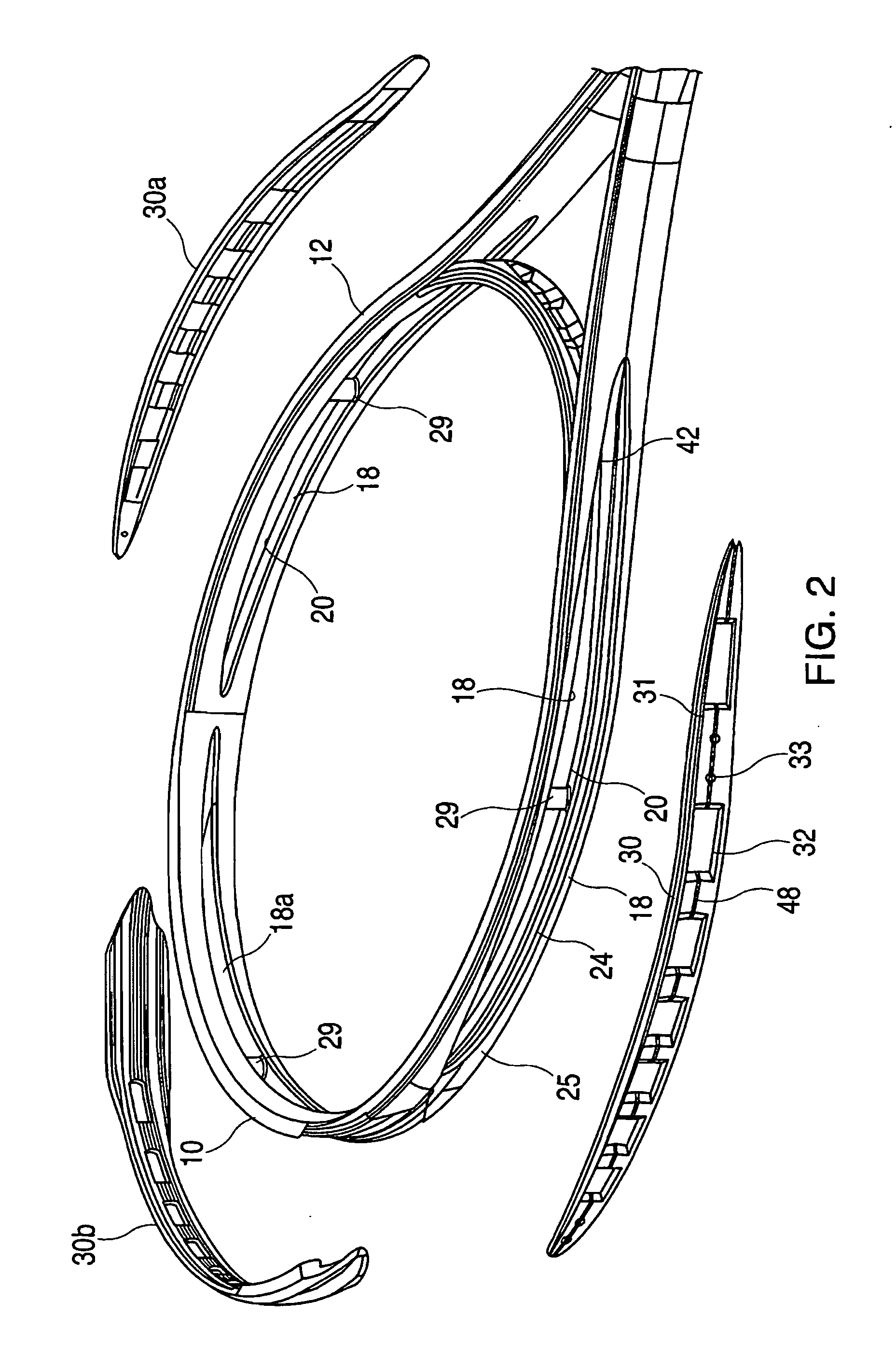
Sports racquet with insert members for anchoring strings
a technology of insert members and racquets, which is applied in the field of sports racquets, can solve the problems of inability to change the playing characteristics of racquets to any significant degree, the racquet is heavier than its original design, and the frame stiffness and the stringing pattern of the racquet cannot be changed
- Summary
- Abstract
- Description
- Claims
- Application Information
AI Technical Summary
Benefits of technology
Problems solved by technology
Method used
Image
Examples
second embodiment
[0051]FIGS. 4-8 illustrate the invention. The opposite sides of the head portion 12a of the frame 10a include cutout portions 18′, and the tip region includes a cutout portion 18a′, each for receiving a cutout member. In addition, the throat bridge 14a includes a cutout portion 18b for receiving another insert member. As shown, the cutout portions 18′, 18a′are not as long as the cutout portions 18, 18a in FIGS. 1-3, and some of the string holes would be drilled or formed in the frame 10a in the regions between the cutout portions. FIG. 7 shows another example of a insert member 30′, which is received in one of the cutout portions 18′, with corresponding insert members being received in the other cutout portions.
third embodiment
[0052]FIGS. 9-10 show a third embodiment in which the inwardly facing walls 50 of the cutout portions 18″, designed to receive insert members, have an undulating shape. As shown in FIG. 10, the insert members 30″have undulating side walls 52 to fit in the cutout portions 18″.
[0053]FIGS. 11-12 show two more embodiments of the invention, in which the sides and tip of the head portion 12c and 12d each have more than one cutout portion 18′″ and 18′″. In the case of FIG. 11, the inwardly facing walls 50c of the cutouts 18′″ are smooth, whereas in FIG. 12 the walls 50d are undulating.
[0054] Preferably, the racquet frame is formed in accordance with a process similar to that described in U.S. published patent application No. US2003 / 0162613, which is incorporated herein by reference. As shown schematically in FIG. 13, a pair of hollow prepreg tubes 60, 61 of uncured composite material are placed between upper and lower mold halves 62, 64 which, when closed, define an inner mold cavity in t...
PUM
 Abstract
Description
Claims
Application Information
 - R&D
- Intellectual Property
- Life Sciences
- Materials
- Tech Scout
- Unparalleled Data Quality
- Higher Quality Content
- 60% Fewer Hallucinations
Browse by: Latest US Patents, China's latest patents, Technical Efficacy Thesaurus, Application Domain, Technology Topic, Popular Technical Reports.
© 2025 PatSnap. All rights reserved.Legal|Privacy policy|Modern Slavery Act Transparency Statement|Sitemap|About US| Contact US: help@patsnap.com


