
External fixation device for osteosynthesis

a fixation device and osteosynthesis technology, applied in invalid friendly devices, medical science, surgery, etc., can solve the problems of inability to precisely guide and define the length of the device, the stability of the frame is impaired, and the complex construction is often expensive to produ

Inactive Publication Date: 2007-05-31
DEPUY SYNTHES PROD INC
View PDF10 Cites 20 Cited by
  • Summary
  • Abstract
  • Description
  • Claims
  • Application Information

AI Technical Summary

Benefits of technology

The present invention provides an external fixation device for osteosynthesis that overcomes the disadvantages of previous devices. The device is stable, can absorb forces reliably, and is simple in design. It allows for easy and simple changes in length. The device includes a frame with rods and clamping jaws connected to the frame via connecting means. A module is provided that can be mounted on the frame and allows for movement of bone fragments relative to each other. The module is delicate and can be left on the frame in the static periods. The method of performing osteosynthesis involves connecting the fixation device to the bone fragments, displacing one of the fragments, and tightening all clamping jaws during a static period. The technical effects of the invention include improved stability, reliable force absorption, and ease of use.

Problems solved by technology

A problem exists in that the external frame firstly must be rigid in order to be able to bear forces and secondly must permit a movement of the fragment in a defined axis (parallel to the extension direction).
The complicated constructions are often expensive to produce.
Furthermore, a disadvantage of telescopic constructional systems is that the stability of the frame is impaired such that telescopic constructional systems generally have to be made comparatively solid in order to ensure that the bearing forces are reliably taken up.
Precise guidance and defined changes in length are not possible with this device.

Method used


Image

  • External fixation device for osteosynthesis
  • External fixation device for osteosynthesis
  • External fixation device for osteosynthesis

Examples


Embodiment Construction

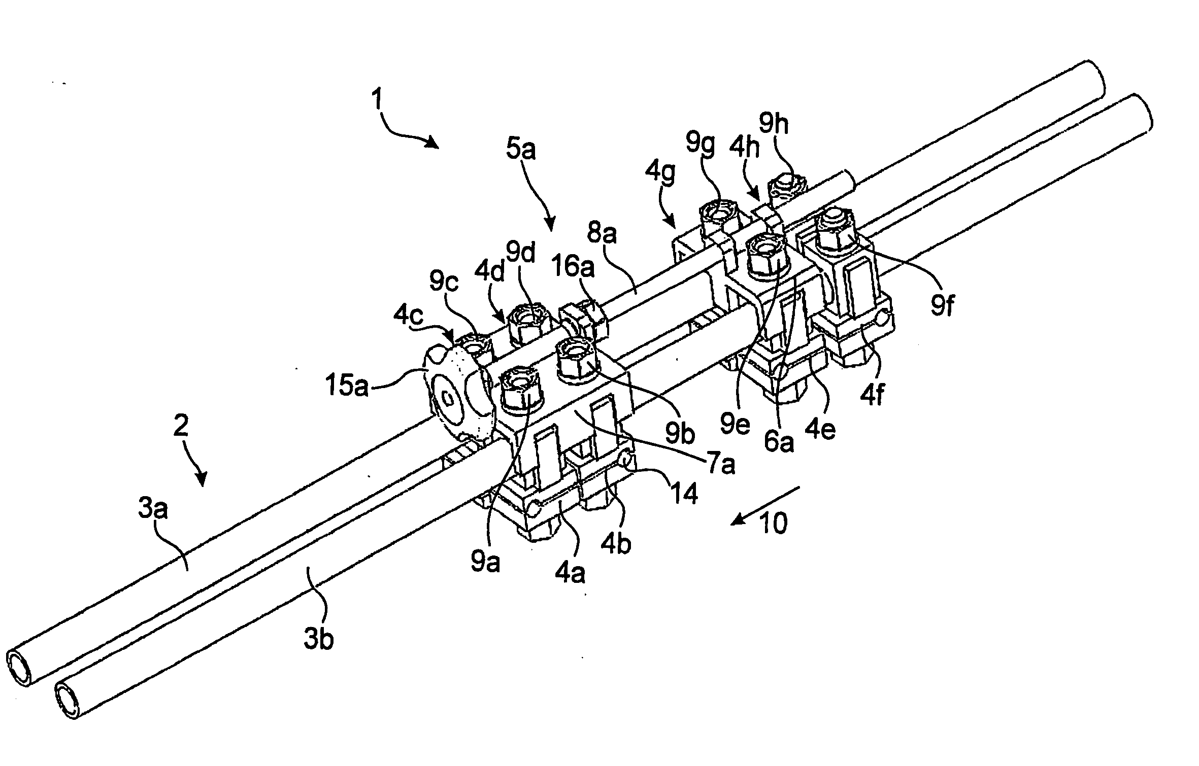
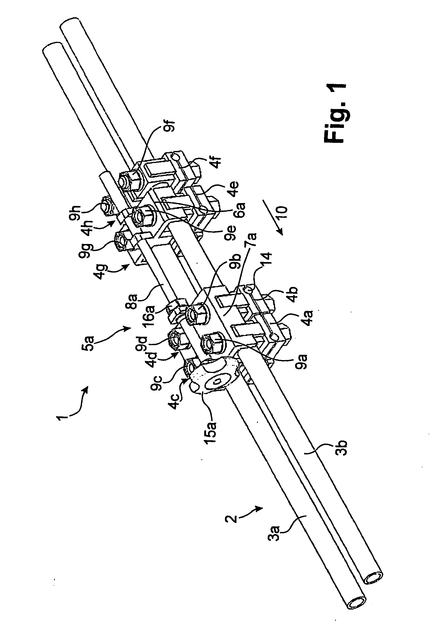
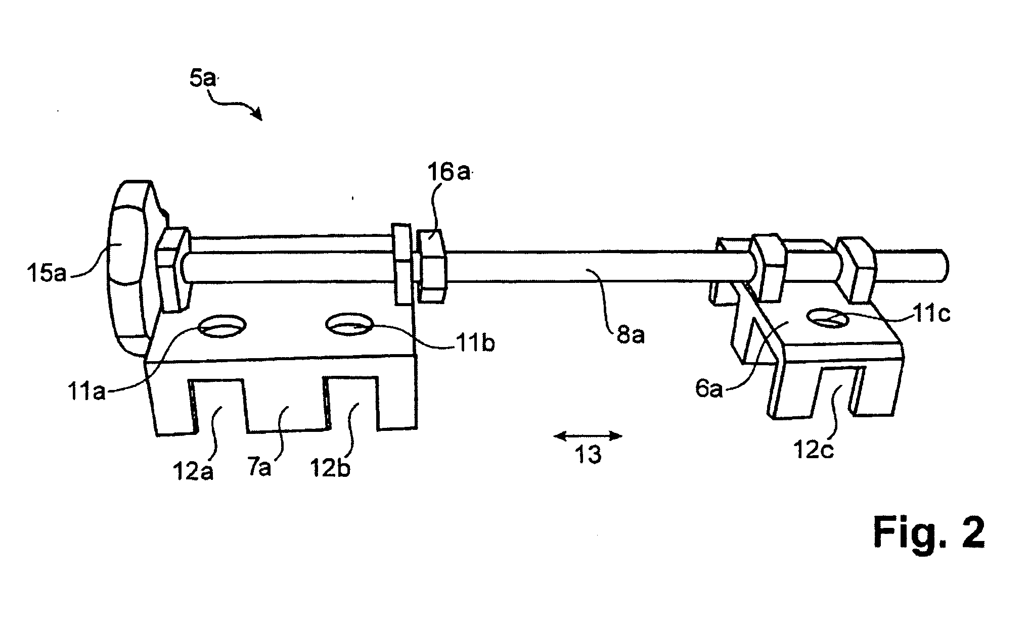
[0021] The fixation device based on a traditional frame having simple, non-telescopic elements. Rods may be used and permit a modular design of various frames. A preferred design is a parallel arrangement of two rods so that a double rail forms. The frame is oriented so that it points in the direction of displacement. Such a frame is provided with clamping jaws on which the bone-retaining pins are fixed. The forces pass via the immobile frame without mechanical displacement units. The actual invention is an additional device, designated as module herein, which is preferably mounted only temporarily to effect an extension increment and, if required, can be removed again at any time without having to remove the entire fixation device.

[0022] The time scheme for an extension procedure may consist of a short extension time (approx. 2 minutes) and a long static time (approx. 6 hours). During the static time, all clamping jaws of the fixation device are tightened and the module is ineffec...


PUM


Abstract

An external fixation device having a frame comprising at least one rod which takes up the mechanical loads. Frame and bone are connected via connecting means known per se, in particular bone-retaining pins. These connecting means in turn are connected to the frame via clamping jaws. These clamping jaws permit detachable fixing and arbitrary arrangement and grouping on the frame. A module which can be mounted on the frame is provided. By means of the module, a movement of two bone fragments relative to one another can be effected. It has at least two components. The first of the at least two components can be connected to the frame. The second of the two components can be connected to at least one clamping jaw of a connecting means which is connected to a bone fragment.

Description

CROSS-REFERENCE TO RELATED APPLICATIONS [0001] This application is a continuation of International Patent Application No. PCT / IB2004 / 000674, filed on Mar. 10, 2004, the entire contents of which are incorporated herein by reference thereto. FIELD OF THE INVENTION [0002] The present invention relates to an-external fixation device and method for osteosynthesis. BACKGROUND OF THE INVENTION [0003] Orthopaedic corrections, such as, for example, limb extension, are carried out nowadays, inter alia, using so-called fixation devices. The proximal end of a bone may be connected by means of bone-retaining pins through the skin to an external frame (located outside the body) which, during the extension process, bears the mechanical loads which are normally borne by the bone. The connection between the screws and the frame is realized by means of clamping jaws. [0004] The distal end of the bone is likewise connected to the external frame by means of bone-retaining pins through the skin. A bone ...

Claims


Application Information

Patent Timeline
Patent Type & Authority Applications(United States)
IPC IPC(8): A61B17/00A61B17/64A61B17/66
CPCA61B17/645A61B17/66A61B17/58A61B17/60
Inventor STRUB, BEATSATIZABAL, CARLOSMUNCH, MARTIN
Owner DEPUY SYNTHES PROD INC
Learn More