Medical Device installation tool and methods of use

a technology for inserting tools and medical devices, applied in the field of tools for inserting prostheses within the body, can solve the problems of limited mobility or freedom of movement, pain, postural problems, injuries, etc., and achieve the effect of maintaining the overall length of the tool

Inactive Publication Date: 2007-05-31
DEPUY SPINE INC (US)
View PDF93 Cites 158 Cited by
  • Summary
  • Abstract
  • Description
  • Claims
  • Application Information

AI Technical Summary

Benefits of technology

[0007] In yet another embodiment, a medical device installation tool can include a housing, a shaft coupled to the housing and a pair of opposed levers, each having a proximal end and a distal end wherein the proximal end of each lever can be pivotably coupled to a portion of the housing such that the distal ends are configured to separate in response to the movement of one or more objects between the levers in the proximal to distal direction. The tool can be selectively configured such that the shaft will translate along a longitudinal axis of the installation tool or will rotate about the longitudinal axis of the installation tool as a result of manipulation of a single driver. For example, the medical device installation tool can include an actuator that can be configured in a first position that allows the driver to effect translation of the shaft along the longitudinal axis of the installation tool, and a second position that allows the driver to effect rotation of the shaft about the longitudinal axis of the installation tool.
[0008] Methods for implanting a prosthetic dev...

Problems solved by technology

Spinal surgery involves many challenges as the long-term health and mobility of the patient often depends on the surgeon's technique and precision.
The insertion of an article, such as an artificial disc prosthesis, presents the surgeon with several challenges.
However, if the vertebral bodies are separated, or distracted, to beyond a certain degree, furt...

Method used


Image

  • Medical Device installation tool and methods of use
  • Medical Device installation tool and methods of use
  • Medical Device installation tool and methods of use

Examples


Embodiment Construction

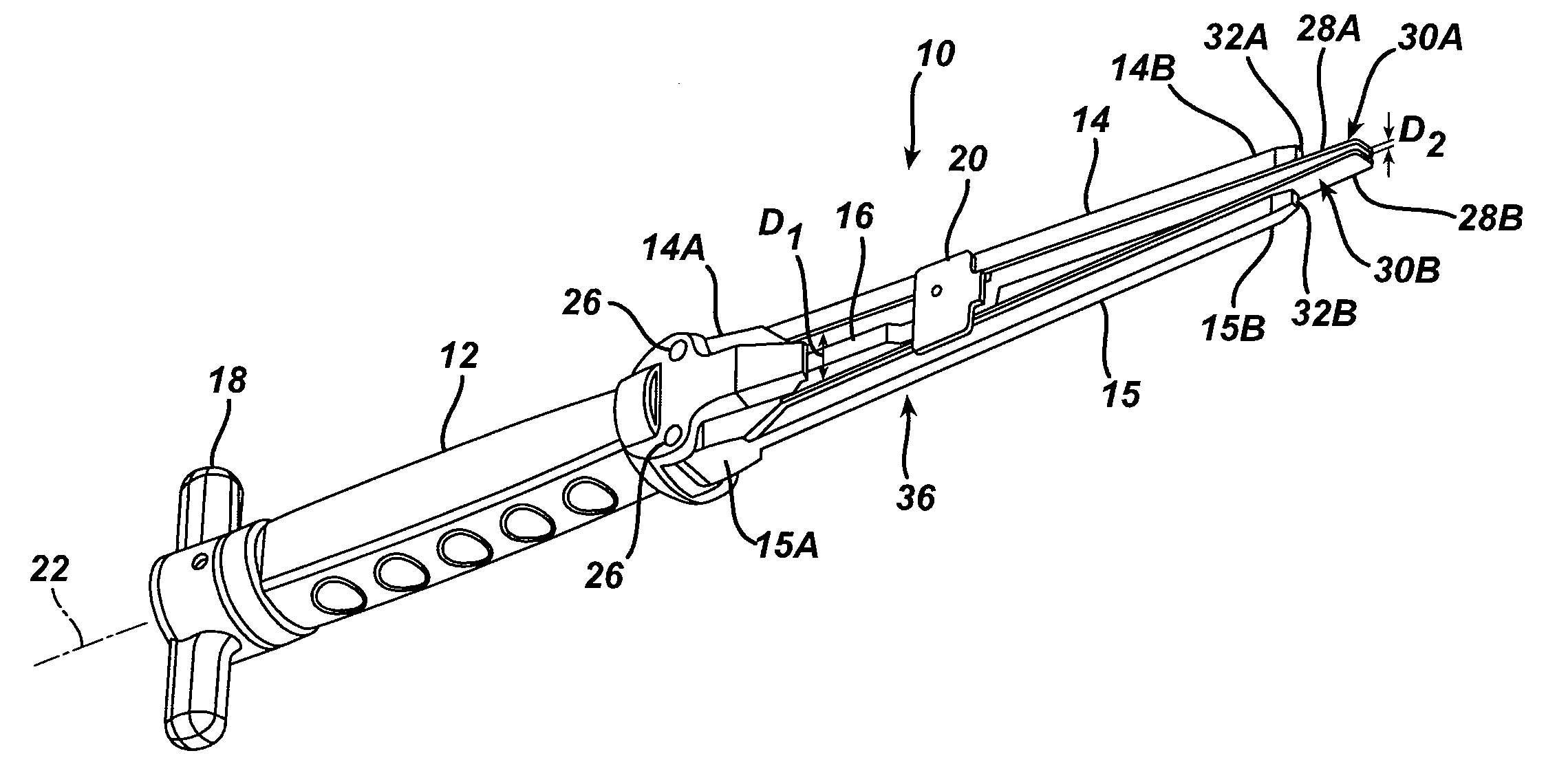
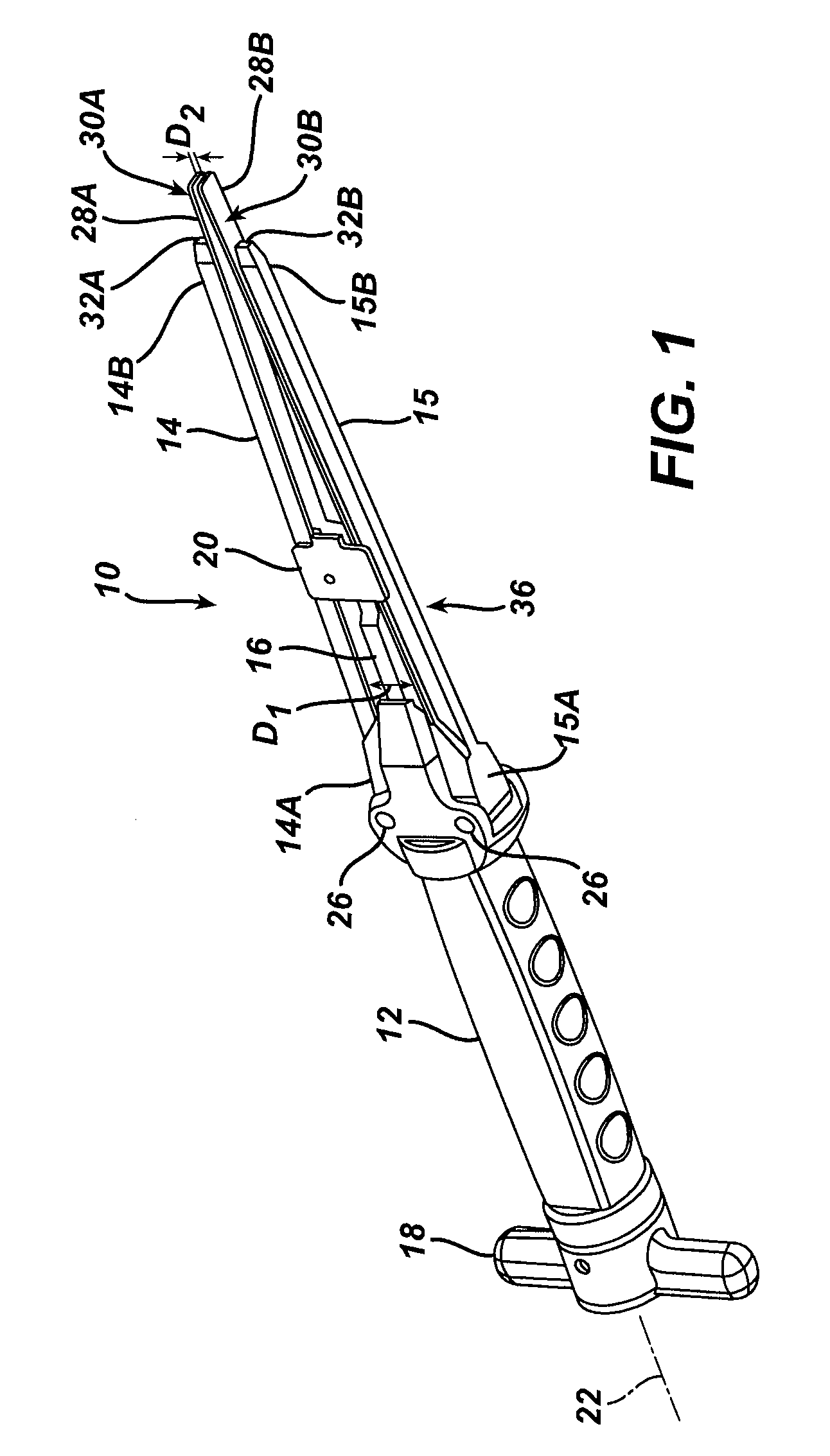
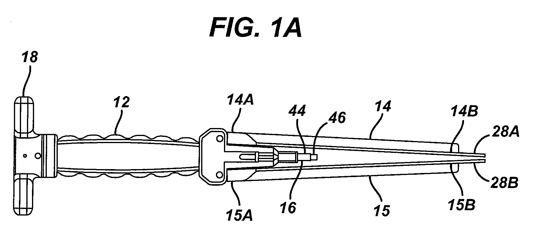
[0024] Certain exemplary embodiments will now be described to provide an overall understanding of the principles, structure, function, manufacture, and use of the devices and methods disclosed herein. One or more examples of these embodiments are illustrated in the accompanying drawings. Those skilled in the art will understand that the devices and methods specifically described herein and illustrated in the accompanying drawings are non-limiting exemplary embodiments and that the scope of the present invention is defined solely by the claims. The features illustrated or described in connection with one exemplary embodiment may be combined with features of other embodiments. Such modifications and variations are intended to be included within the scope of the present invention.

[0025] The present invention provides a medical device installation tool for implanting a prosthetic device, such as a spinal implant, between adjacent vertebral bodies. In general, the installation tool incl...


PUM


Abstract

Methods and devices for implanting a prosthetic device, such as an artificial spinal implant, are provided. The installation tool can include a handle having a pair of opposed levers, an optional pusher block disposed between the levers, and a shaft at least partially disposed within the handle and able to be coupled to the pusher block and/or to a prosthetic device. As the shaft translates along a longitudinal axis of the installation tool, the pusher block and/or the prosthetic device separate the levers and distract adjacent vertebral bodies to position a prosthetic device therebetween. The tool is able to maintain its an overall length during use, and it can be configured in rotation and/or translation modes.

Description

FIELD OF THE INVENTION [0001] The invention relates broadly to a tool for inserting a prosthesis within a body, and more particularly to a tool for inserting prostheses, such as artificial discs or other implants within an intervertebral space. BACKGROUND OF THE INVENTION [0002] Spinal surgery involves many challenges as the long-term health and mobility of the patient often depends on the surgeon's technique and precision. One type of spinal surgery involves the removal of the natural disc tissue that is located between adjacent vertebral bodies. Procedures are known in which the natural, damaged disc tissue is replaced with an interbody cage or fusion device, or with a disc prosthesis. [0003] The insertion of an article, such as an artificial disc prosthesis, presents the surgeon with several challenges. The adjacent vertebral bodies collapse upon each other once the natural disc tissue is removed. These bodies must be separated to an extent sufficient to enable the placement of t...

Claims


Application Information

Patent Timeline
IPC IPC(8): A61F2/00
CPCA61B2017/0256A61F2/442A61F2/4611A61F2002/4627A61F2002/4628A61F2002/4629
Inventor RAYMOND, DOUGLASHOYLE, CRAIGWHITE, SHINIKEQUA
Owner DEPUY SPINE INC (US)
Why Eureka
Try Eureka