Cable-driven manipulator

a manipulator and cable technology, applied in the direction of manufacturing tools, gearing, hoisting equipment, etc., can solve the problems of slipping objects, damage to gripped objects, etc., and achieve the effect of constant length and precise position control of end effectors

Active Publication Date: 2009-06-11
KOREA ATOMIC ENERGY RES INST
View PDF3 Cites 13 Cited by
  • Summary
  • Abstract
  • Description
  • Claims
  • Application Information

AI Technical Summary

Benefits of technology

[0018]Therefore, it is an object of the present invention to provide a cable-driven manipulator that can prevent the change of tensile force due to the change of the length of the cable for operating the end effector, or an unintended malfunction of the end effector. It is another object of the invention to make precise position control of the end effector possible, by means of a cable compensation device installed between an upper arm and a forearm of the manipulator, so as to maintain the length of cable constant even during the pivoting of the forearm.

Problems solved by technology

In particular, such an interference phenomenon can cause the gripped object to fall down when the cable 5 driving the gripper 4 is unwound, or the gripped object can be damaged due to excessive tensile force.

Method used


Image

  • Cable-driven manipulator
  • Cable-driven manipulator
  • Cable-driven manipulator

Examples


Embodiment Construction

[0040]Reference will now be made in detail to the embodiments of the present invention, examples of which are illustrated in the accompanying drawings.

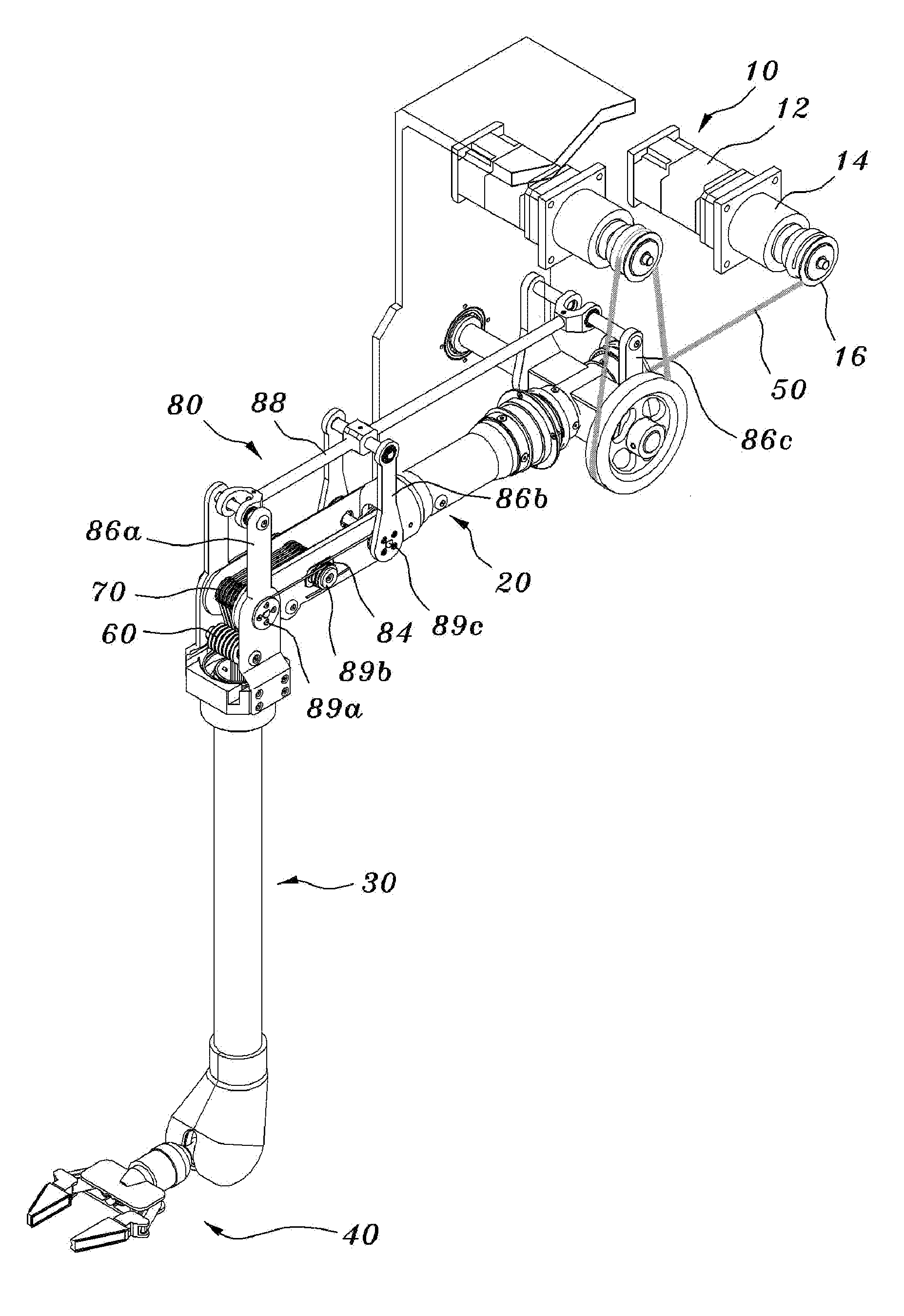
[0041]FIGS. 4A and 4B are a perspective view and a plan view showing the cable-driven manipulator according a preferred embodiment of the present invention, respectively. FIG. 5A is a plan view schematically showing the operation of the cable-driven manipulator according to the preferred embodiment of the present invention. FIGS. 5B and 5C are lateral views schematically showing the operation of the cable-driven manipulator according to the preferred embodiment of the present invention, respectively. FIGS. 6A to 6D are schematic views showing various arrangements of the fourth to sixth pulleys provided in the cable-driven manipulator according to the preferred embodiment of the present invention.

[0042]As shown in FIGS. 4A to 6A, the cable-driven manipulator according to the preferred embodiment of the present invention comprises an op...


PUM


Abstract

The present invention discloses a cable-driven manipulator comprising an operating unit having a drive motor, and a pulley rotated by the drive motor. An upper arm is coupled, through a joint, to one side of the operating unit. A forearm coupled, through a joint, to the other side of the upper arm by the cable. A gripper of an end effector operably coupled to the forearm, a cable compensation device is installed between the upper arm and the forearm so as to maintain constant the length of the cable that transmits the power of the operating unit to the end effector during the pivoting of the forearm. It is thus possible to prevent the variation of tensile force due to the variation of the length of the cable for operating the end effector during the pivoting of the forearm or the unintended malfunction of the end effector.

Description

BACKGROUND OF THE INVENTION[0001]This application claims priority to Korean Patent Application No. 10-2007-0125586, filed on Dec. 5, 2007, and Korean Patent Application No. 10-2008-0112545, filed on Nov. 13, 2008, the entire contents of which are hereby incorporated by reference.FIELD OF THE INVENTION[0002]The present invention relates to a cable-driven manipulator, more specifically to a cable-driven manipulator, in which a cable compensation device is installed between an upper arm and a forearm and is configured so that a length of a cable wound on the pulley provided in the operating unit to operate an end effector is maintained constant even during the pivoting of the forearm. This makes it possible to prevent a variation of tensile force due to a variation of the length of the cable for operating the end effector during the pivoting of the forearm and also prevents an unintended malfunction of the end effector.DESCRIPTION OF THE RELATED ART[0003]In general, master-slave manipu...

Claims


Application Information

Patent Timeline
Patent Type & Authority Applications(United States)
IPC IPC(8): B66C3/14B66C3/06
CPCY10T74/20323B25J9/1045
Inventor LEE, JONG KWANGCHOI, CHANG HWANYOON, KWANG HOLEE, HYO JIKPARK, BYUNG SUKYOON, JI SUP
Owner KOREA ATOMIC ENERGY RES INST
Why Eureka
Try Eureka