
Non-penetrating fixing device

a fixing device and non-penetrating technology, applied in the field of non-penetrating fixing devices, can solve the problems of surgical errors, incur the drawback of being forced to penetrate and thus injure the patient's body, and achieve the effect of minimally invasive operating techniques

Inactive Publication Date: 2007-05-31
BRAINLAB
View PDF64 Cites 112 Cited by
  • Summary
  • Abstract
  • Description
  • Claims
  • Application Information

AI Technical Summary

Benefits of technology

[0005] The present invention provides a fixing device and method that enables minimally invasive operating techniques. The present invention also provides a fixing device that can be fixed to a bone without penetrating and injuring the bone. The present invention further provides a fixing device that enables the surgeon to insert the fixing device through a small soft-tissue portal in the patient.
[0008] Accordingly, one benefit of the present invention is that the fixing device can be fixed to a patient's bone without penetrating the bone tissue. Furthermore, it is possible to connect and detach elements of the fixing device such that they may be introduced into the patient's body through a comparatively small portal in the soft-tissue of the patient's body.
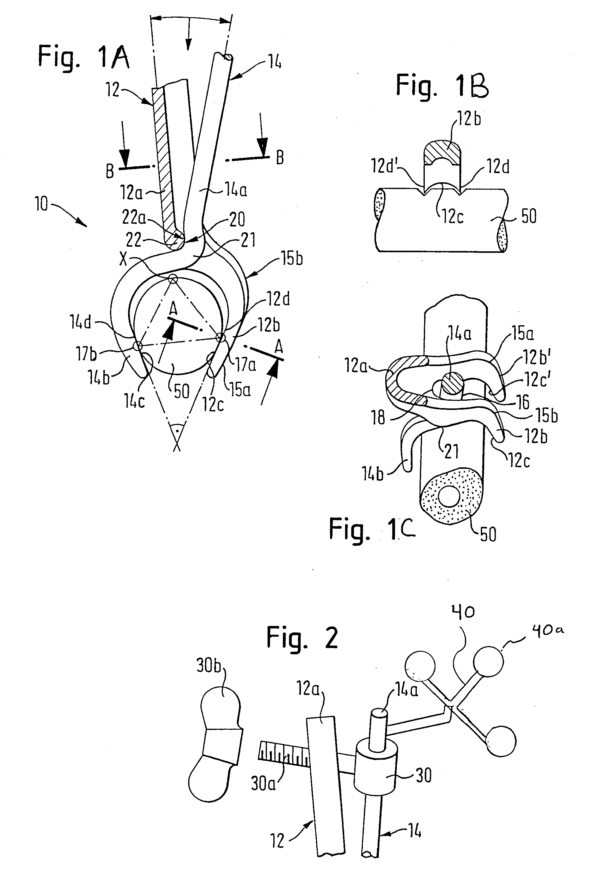
[0010] One of the first and second lever elements can include a receiving section and the other can include an insertion section. The insertion section can be removably introduced into the receiving section such that the insertion section may be pivoted with respect to the receiving section. This construction allows the fixing device to be assembled in the surgical field (e.g., in the patient's body), wherein the parts of the fixing device can be separately introduced and removed from the patient's body. When assembled within the surgical field, the parts can have the general shape of pliers.
[0015] The gripping surface or gripping surfaces can be broadened in a direction perpendicular to the main extension of the corresponding lever element and / or can be provided with at least one, preferably two extended edges directed towards the opposite gripping surface. This provides a further safety aspect that ensures the device cannot be displaced, rotated or the like, such that the reference elements or the reference array cannot be improperly positioned or located.
[0018] It may be beneficial to ensure that the device is fixed to a bone such that at least three portions or three areas of the device are in direct contact with corresponding parts of the bone. This prevents the device from being rotated once it has been fixed to the bone.
[0019] Accordingly, the present invention enables a surgeon to attach a device and in particular a reference element or reference array to a surgical field, and in particular to a bone structure of a patient. Reference element or reference arrays are commonly used for image-guided surgery. The fixing device prevents translational and rotational displacements of the reference element or reference array or of any other surgical equipment which is fixed by means of the device. The device can be used in connection with computer aided and / or image guided surgical systems such as Vector Vision and / or Trauma 2.5, both well known products of the assignee of the present application.

Problems solved by technology

Improperly locating the reference element or reference array may direct the surgeon away from the actual situation in the surgical field and can cause surgical errors.
This group incurs the drawback that it is necessary to penetrate and thus injure a patient's body.

Method used


Image

  • Non-penetrating fixing device
  • Non-penetrating fixing device

Examples


Embodiment Construction

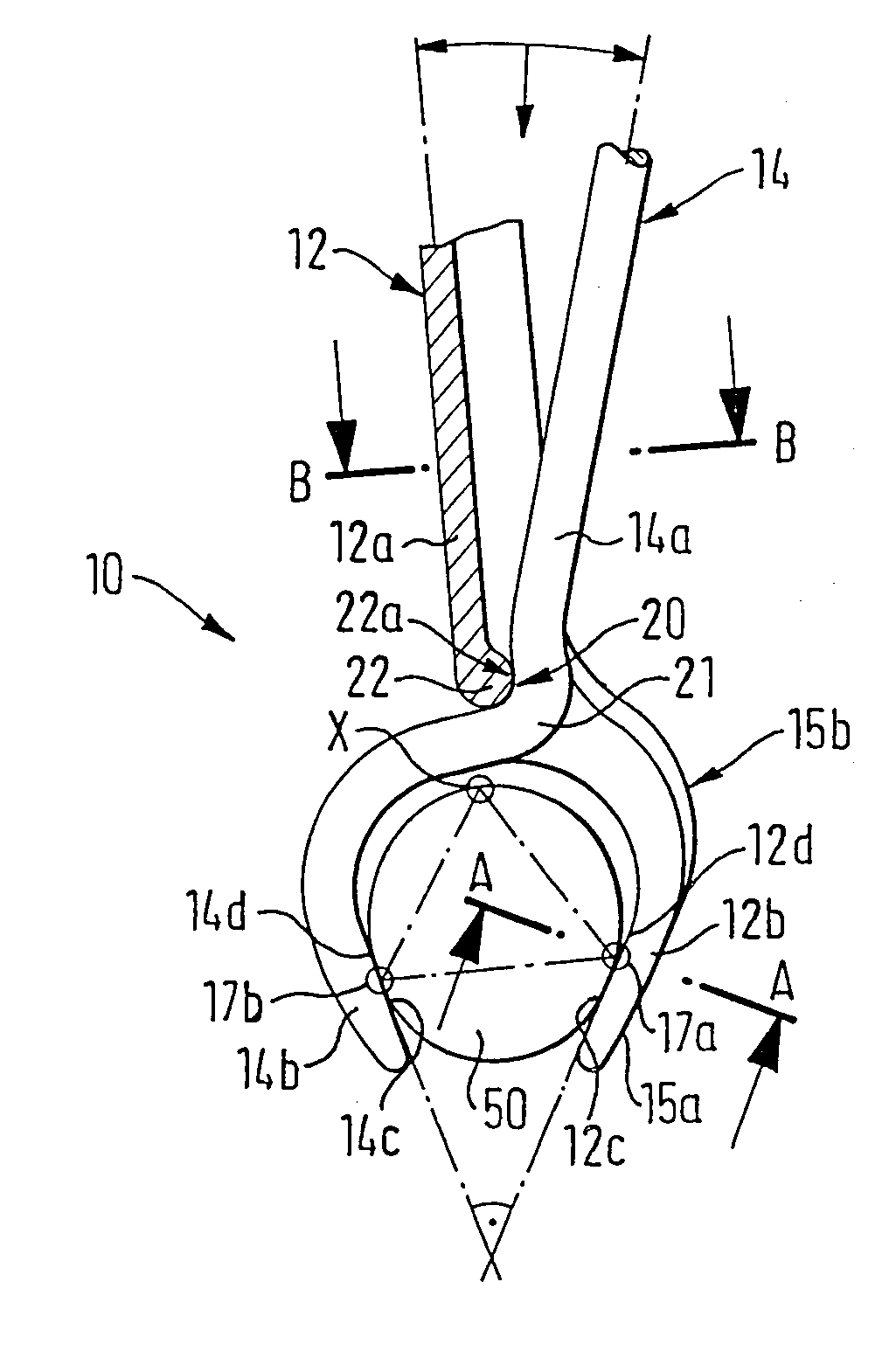
[0027] An exemplary fixing device according to FIG. 1A is indicated generally by reference indicator 10. Since the illustrated fixing device functions much like pliers to grip a body part, such as a bone, such fixing device is herein referred to as pliers. The skilled person will appreciate, however, that a fixing device according to the invention may take other forms as well.

[0028] The pliers 10 include a first lever element 12 and a second lever element 14 that are assembled to form the pliers 10. A surgeon's hand can grip the pliers at first and second handling portions 12a and 14a of the first and the second lever element 12 and 14. A bone 50 can be gripped or clamped by means of first gripping portion 14b of lever element 14 and second gripping portion as shown, the second gripping portion including two laterally spaced apart parts 12b and 12b′.

[0029] When introducing the elements of the pliers 10 into the surgical field in a patient's body, a surgeon may first introduce the ...


PUM


Abstract

A fixing device for securely fixing surgical equipment to a surgical field of a human or animal body includes a first lever element including a first gripping portion and a first handling portion, and a second lever element including a second gripping portion and a second handling portion. The and second lever elements can be connected such that they can be pivoted and detached with respect to each other.

Description

RELATED APPLICATION DATA [0001] This application claims priority of U.S. Provisional Application No. 60 / 754,510 filed on Dec. 28, 2005, which is incorporated herein by reference in its entirety.FIELD OF THE INVENTION [0002] The present invention relates to a device for securely fixing surgical equipment to a surgical field of a human or animal body, in particular a bone. Furthermore, the invention is related to a method for introducing a fixing device into a surgical field. BACKGROUND OF THE INVENTION [0003] Modern surgical procedures utilize improved accuracy to guarantee a minimally invasive operation, such that the patient is able to quickly recover from surgery. Therefore, surgical procedure are used that incur a minimal injury to the patient's body. To avoid injuring the patient's body during a surgical operation, the accuracy of the surgery is enhanced, and the surgery itself is performed so as to minimize entry into the body (which may not allow the surgeon to directly view t...

Claims


Application Information

Patent Timeline
IPC IPC(8): A61B17/08
CPCA61B17/8866A61B2019/5483A61B2090/3983
Inventor MAIER, CHRISTIANMAIER, GEORG
Owner BRAINLAB
Learn More