Scan driver and organic light emitting display device

a technology of light-emitting display device and scan driver, which is applied in the direction of measurement device, electronic circuit testing, instruments, etc., can solve the problems of increasing manufacturing costs and further increasing manufacturing costs, and achieve the effect of reducing the number of output lines of data drivers

Active Publication Date: 2007-05-31
SAMSUNG DISPLAY CO LTD
View PDF2 Cites 86 Cited by
  • Summary
  • Abstract
  • Description
  • Claims
  • Application Information

AI Technical Summary

Benefits of technology

[0013] An aspect of the present invention is to provide a scan driver and a organic light emitting display device, in which a number of output lines of a data driver can be reduced.

Problems solved by technology

Accordingly, multiple data driving circuits may be included in the data driver 20 so that the data driver 20 can drive m output lines, which may lead to increased manufacturing costs.
In particular, as a resolution and a size (e.g., in inches) of an organic light emitting display device increase, a data driver 20 of the conventional organic light emitting display device is required to drive a correspondingly higher number of output lines, which may further increase manufacturing costs.

Method used


Image

  • Scan driver and organic light emitting display device
  • Scan driver and organic light emitting display device
  • Scan driver and organic light emitting display device

Examples


Embodiment Construction

[0032] In the following detailed description, only certain exemplary embodiments of the present invention are shown and described, by way of illustration. As those skilled in the art would recognize, the described exemplary embodiments may be modified in various ways, all without departing from the spirit or scope of the present invention. Accordingly, the drawings and description are to be regarded as illustrative in nature, and not restrictive.

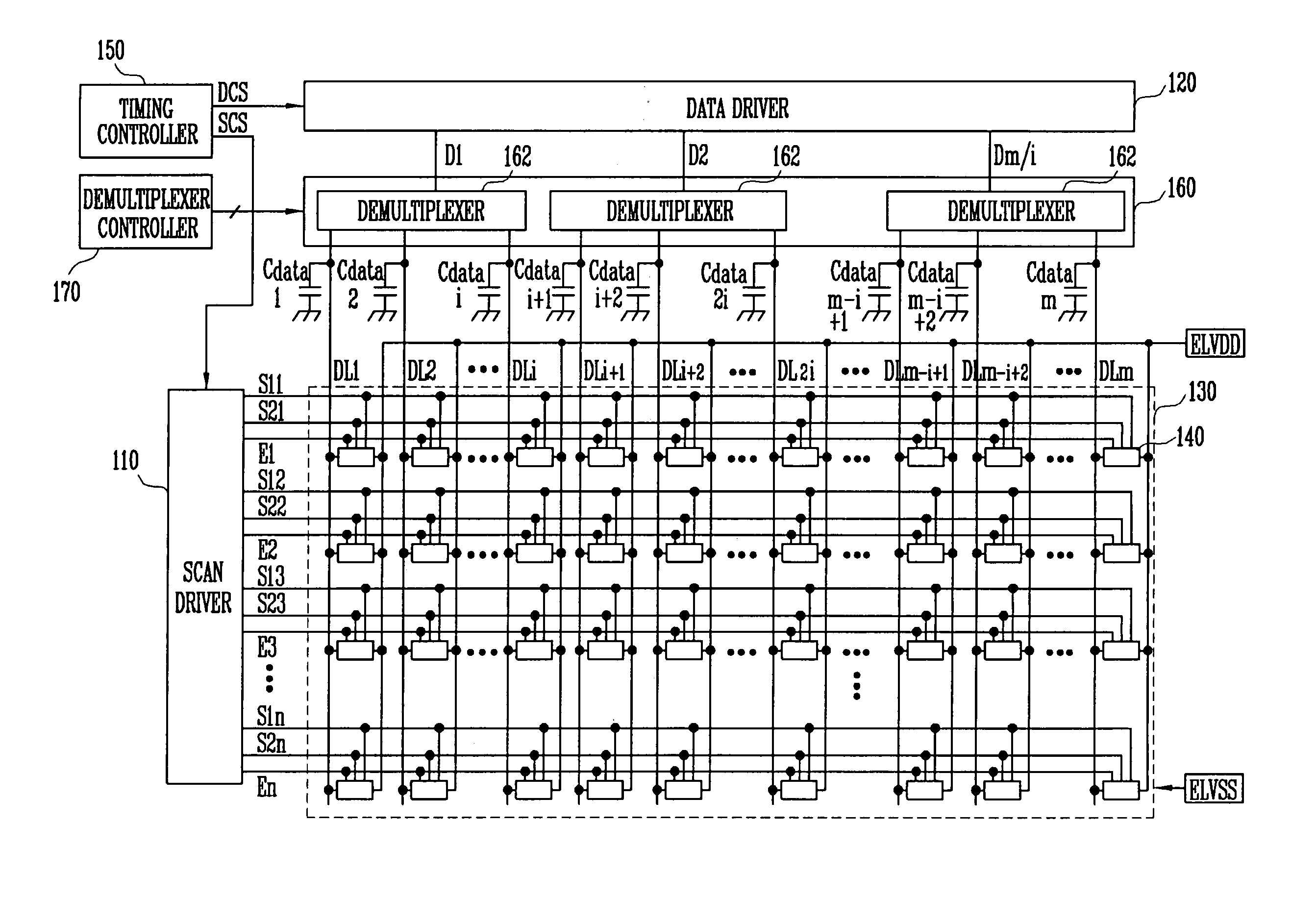
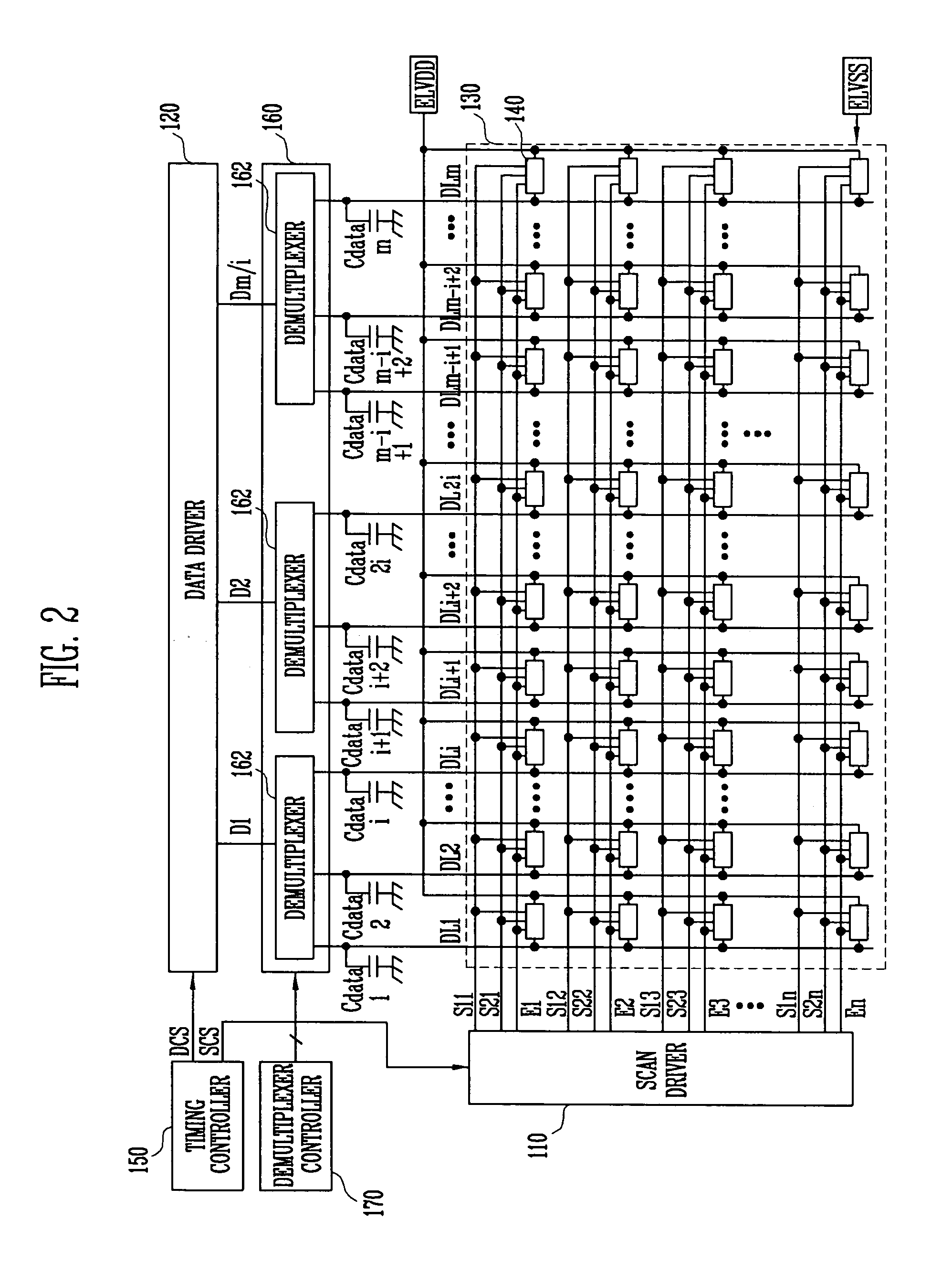
[0033]FIG. 2 is a diagram showing an organic light emitting display device according to an embodiment of the present invention.

[0034] Referring to FIG. 2, the organic light emitting display device includes a scan driver 110, a data driver 120, a display region 130, a timing controller 150, a demultiplexer unit 160, a demultiplexer controller 170, and a plurality of data capacitors Cdata.

[0035] The display region 130 includes a plurality of pixels 140, each of which is arranged to be connected with one of first scan lines S11, S12, . . . ,...


PUM


Abstract

An organic light emitting display device includes a scan driver for supplying a first scan signal to a first scan line during a first period and a second period, a second scan signal to a second scan line during the second period, and a light emitting control signal to a light emitting control line during a period at least spanning the first and second periods. A data driver sequentially supplies data signals to an output line during the first period. A demultiplexer is electrically coupled to the output line, receives the data signals and supplies the data signals to data lines which are connected to pixels. Each pixel receives one of the data signals during the first period, compensates a threshold voltage of a driving transistor during the second period, and generates light with a brightness corresponding to the one of the data signals after the second period.

Description

CROSS-REFERENCE TO RELATED APPLICATIONS [0001] This application claims priority to and the benefit of Korean Patent Application Nos. 10-2005-0107197 and 10-2005-0107198, both filed on Nov. 9, 2005, in the Korean Intellectual Property Office, the entire contents of which are incorporated herein by reference. BACKGROUND [0002] 1. Field of the Invention [0003] The present invention relates to a scan driver and an organic light emitting display device, and, more particularly, to a scan driver and an organic light emitting display device which uses a reduced number of data driver output lines. [0004] 2. Discussion of Related Art [0005] One type of flat panel display device is an organic light emitting display device which displays images by using an organic light emitting diode (OLED). The OLED generates light by recombining electrons and holes. Advantages of the organic light emitting display device include rapid response speed and low consumption of power. [0006]FIG. 1 is a diagram sho...

Claims


Application Information

Patent Timeline
Patent Type & Authority Applications(United States)
IPC IPC(8): G01R31/28
CPCG09G3/2003G09G3/3233G09G3/3266G09G2300/0819G09G2300/0842G09G2300/0861G09G2310/0205G09G2310/0262G09G2310/0297G09G2330/021
Inventor KIM, YANG WAN
Owner SAMSUNG DISPLAY CO LTD
Why Eureka
Try Eureka