Collapsible container

a container and lid technology, applied in the field of collapsible containers, can solve the problem that the side walls cannot be easily collapsed during the washing process, and achieve the effect of preventing unintended collapsing walls

Inactive Publication Date: 2007-06-07
LINPAC MATERIALS HANDLING
View PDF7 Cites 37 Cited by
  • Summary
  • Abstract
  • Description
  • Claims
  • Application Information

AI Technical Summary

Benefits of technology

[0030] Preferably, the stacking element is pivotally attached to the shorter wall. The stacking element may include locking elements that are constructed and arranged to engage the longer walls when deployed, to prevent unintended collapse of the walls.

Problems solved by technology

First, because the end walls have to be folded before the side walls, the side walls cannot easily collapse during the washing process.

Method used


Image

  • Collapsible container
  • Collapsible container
  • Collapsible container

Examples


embodiment 1

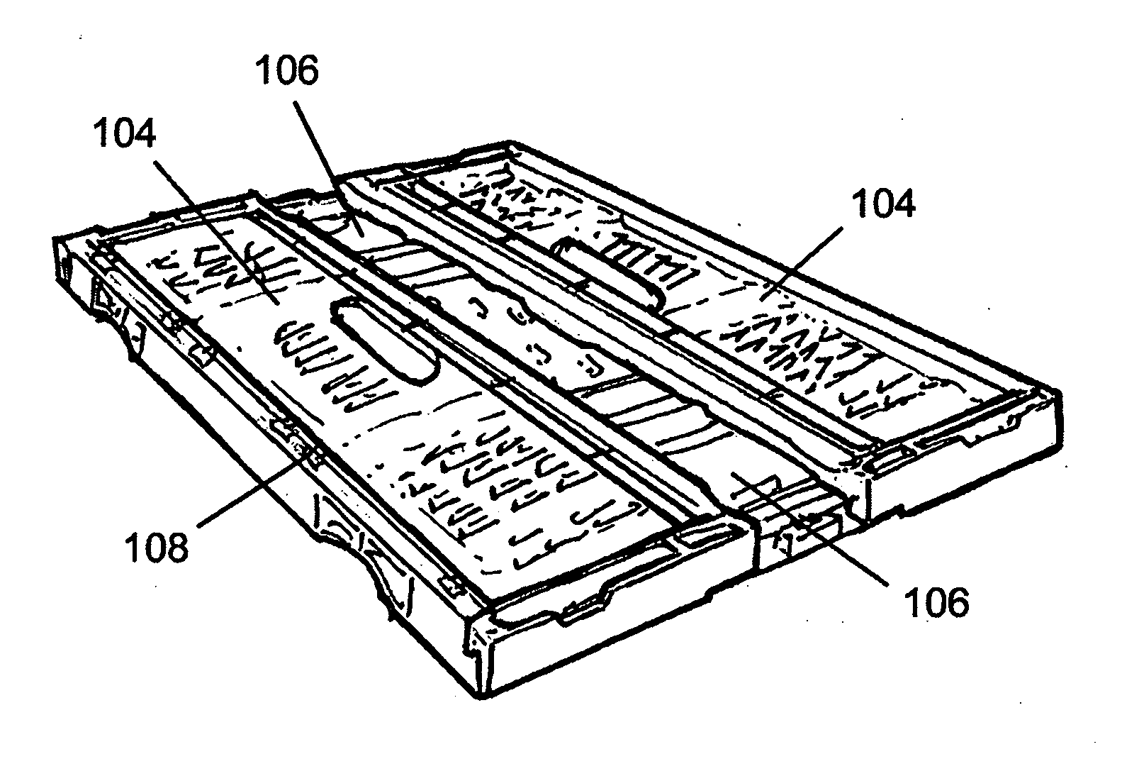
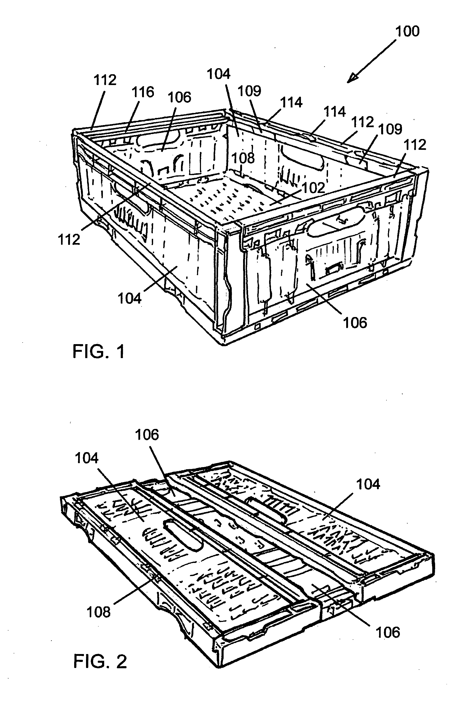
[0079] The first container 100 shown in FIGS. 1-6 comprises a substantially rectangular base 102, two longer side walls 104 and two shorter end walls 106. The side walls and the end walls are attached to the base 102 by means of hinges 108, which allow the walls to be folded flat onto the base 102 for storage or transportation in a collapsed condition, as shown in FIG. 2. It will be noted that the end walls 106 are folded first and that in the collapsed condition they lie adjacent to the base 102. The length of the end walls 106 is less than the separation of the erected side walls 104, so that the end walls can pivot between the side walls. The side walls 104 are collapsed after the end walls 106 and in the collapsed condition overlie the end walls 106. Recesses 109 are provided where necessary in the side walls to allow them to lie flat against the end walls.

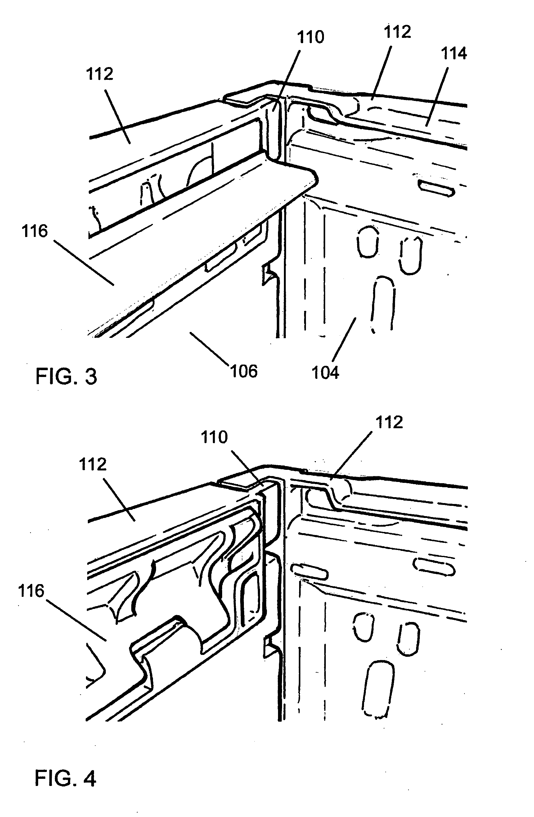
[0080] Complementary locking formations 110 in the form of resilient detents are provided on the end walls and the side wal...

embodiment 2

[0088] The second container 200 shown in FIGS. 7-12 comprises a substantially rectangular base 202, two side walls 204 and two end walls 206. The side walls and the end walls are attached to the base 202 by means of hinges 208, which allow the walls to be folded flat onto the base 202 for storage or transportation in a collapsed condition, as shown in FIG. 8. It will be noted that the end walls 206 are folded first and that in the collapsed condition they lie adjacent to the base 202. The side walls 204 are collapsed after the end walls 206 and in the collapsed condition overlie the end walls 206.

[0089] Complementary locking formations 210 are provided on the end walls and the side walls, to lock the walls together when the container is in the erected condition as shown in FIG. 7. The locking formations 210 are conventional and will not be described in detail.

[0090] The upper edges 212 of the side walls 204 and the end walls 206 are designed to receive the edges of the base 202 of...

embodiment 3

[0098] The third container 300 shown in FIGS. 13-18 is similar in many respects to the second container and comprises a substantially rectangular base 302, two side walls 304 and two end walls 306. The side walls and the end walls are attached to the base 302 by means of hinges 308, which allow the walls to be folded flat onto the base 302 for storage or transportation in a collapsed condition, as shown in FIG. 14. It will be noted that the end walls 306 are folded first and that in the collapsed condition they lie adjacent to the base 302. The side walls 304 are collapsed after the end walls 306 and in the collapsed condition overlie the end walls 306.

[0099] Complementary locking formations are provided on the end walls and the side walls, to lock the walls together when the container is in the erected condition as shown in FIG. 13. The locking formations are conventional and will not be described in detail.

[0100] The upper edges 312 of the side walls 304 and the end walls 306 ar...


PUM


Abstract

A collapsible container that may be configured in a collapsed condition or an erected condition, including a base (102), a pair of side walls (104) and a pair of side walls (106) that are pivotally attached to the base. The walls (104,106) are arranged to lie substantially parallel with the base (102) when collapsed and to stand substantially perpendicular to the base when erected. The free edges of the erected walls define an open mouth. A pair of stacking elements (116) are located adjacent to the free edges of the end walls (106) for supporting the base of another container stacked on the first container. The end walls (106) lie adjacent the base (102) and side walls (104) overlie the end walls when collapsed.

Description

CROSS-REFERENCE TO RELATED APPLICATIONS [0001] This application claims priority under 35 U.S.C. 119 to Great Britain Patent Application Nos. 0600164.8, filed Jan. 6, 2006; and 0522341.7, filed Nov. 2, 2005, the entire contents of which are incorporated by reference in their entireties. BACKGROUND OF THE INVENTION [0002] 1. Field of the Invention [0003] The present invention relates to a collapsible container that is suitable for stacking. [0004] 2. Description of the Related Art [0005] Stacking containers are widely used in the retail industry for transporting produce such as fresh fruit and vegetables from the growers to the shops, and for displaying those goods for sale. The containers protect the goods during transportation and storage and may be stacked for efficient handling and storage. After the goods have been sold, the containers are washed and returned for re-filling. [0006] In order to minimise shipping costs when returning the empty containers, they are normally designed...

Claims


Application Information

Patent Timeline
Patent Type & Authority Applications(United States)
IPC IPC(8): B65D6/00
CPCB65D11/1833B65D21/06B65D21/062
Inventor COPE, ANDREW CHRISTOPHER
Owner LINPAC MATERIALS HANDLING
Why Eureka
Try Eureka