Method for creation of inclined microstructures using a scanned laser image

Inactive Publication Date: 2001-11-06
IBM CORP +1
View PDF11 Cites 40 Cited by
  • Summary
  • Abstract
  • Description
  • Claims
  • Application Information

AI Technical Summary

Problems solved by technology

The prior art does not easily control the inclination of angle and depth of the microstructures for application in photonic circuitry.
Speci

Method used


Image

  • Method for creation of inclined microstructures using a scanned laser image
  • Method for creation of inclined microstructures using a scanned laser image
  • Method for creation of inclined microstructures using a scanned laser image

Examples


Embodiment Construction

)

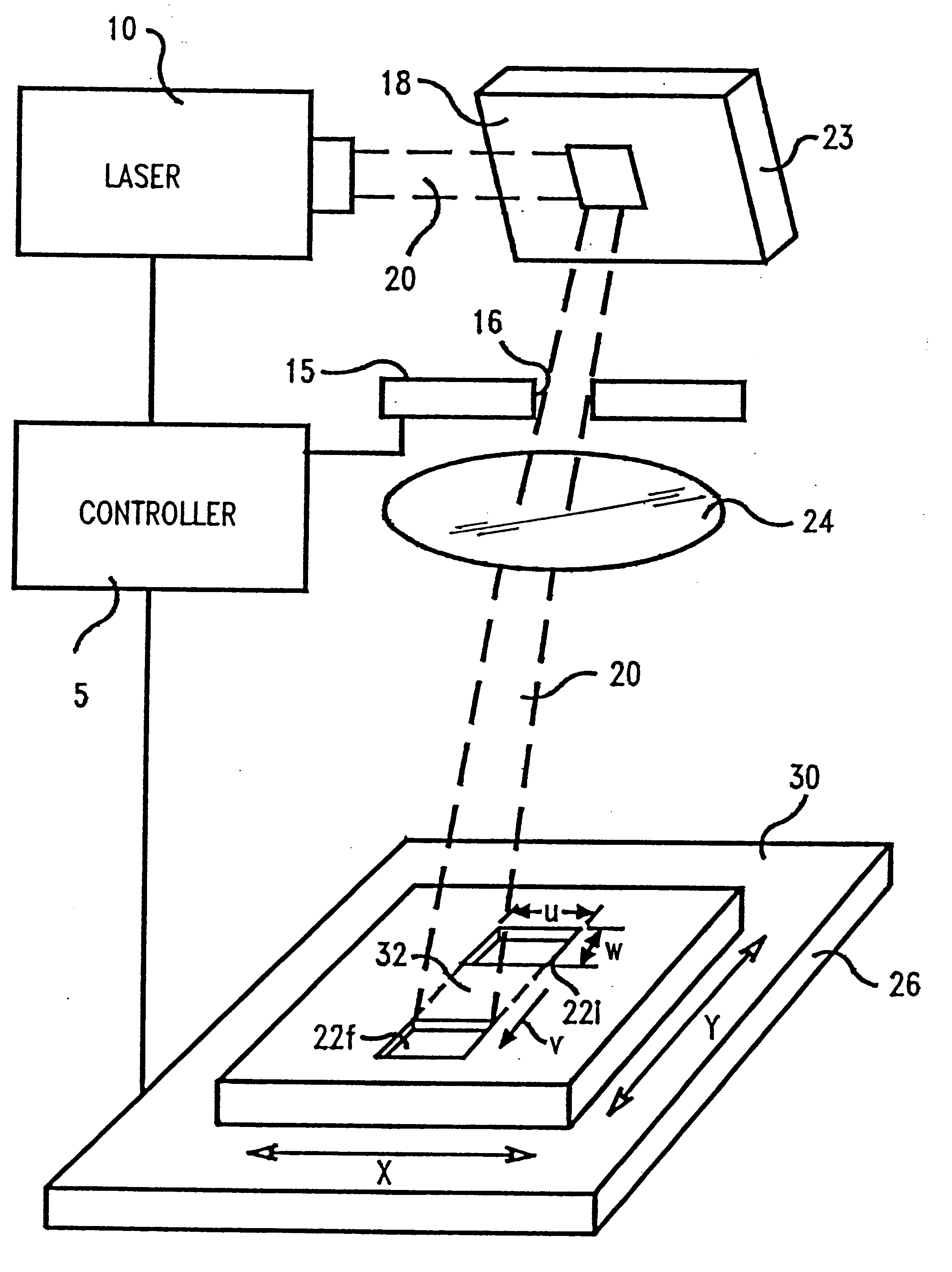
In describing the preferred embodiment of the present invention, reference will be made herein to FIGS. 1-7 of the drawings in which like numerals refer to like features of the invention. Features of the invention are not necessarily shown to scale in the drawings.

The present invention is directed to a system and method of ablation of material from a workpiece with an energy beam such as a laser or electron beam. Preferably, an excimer laser of suitable wavelength for material removal is used to evenly illuminate an aperture of fixed or variable size. Optics produce an image of the aperture at the surface to be machined, and a means for translating or moving the image relative to the plane of the workpiece surface at a constant velocity is provided. Control means for gating the laser illumination on and off at specific times or at specific locations are also provided.

The present invention may be used to cut microstructures in polymer planar waveguides, ceramic semiconductor wafer s...


PUM

PropertyMeasurementUnit
Lengthaaaaaaaaaa
Microstructureaaaaaaaaaa
Dimensionaaaaaaaaaa

Abstract

A system for controlling inclination and depth of ablation of a polymer planar waveguide or semiconductor wafer substrate utilizes a laser which directs the beam at the substrate to ablate portions of the surface thereof and a translatable stage for moving the substrate relative to the beam to create a path of ablated material from the surface. The velocity of the substrate is controlled relative to ablation rate of material from the surface or the dimension of the beam is controlled along the path of ablated material to create a desired inclination and depth of ablated material in the path. The depth of ablated material is a function of the beam width along the path of ablated material, workpiece velocity and ablation rate and is substantially controlled by the formula:where D is the depth of ablated material, R is ablation rate, W is beam dimension along the path of ablated material, and V is workpiece velocity.

Description

1. Field of the InventionThis invention relates to the processing of workpieces with an energy beam and more particularly to creation of controlled inclined trenches and other microstructures in semiconductor wafers or polymer planar waveguides using a scanned laser.2. Description of Related ArtInclined surfaces in microstructures of semiconductor wafer substrates or polymer planar waveguides have been produced using image projection of stationary apertures of variable size, such that the aperture dimensions change while the laser is firing, or raster scanning a focused spot, increasing the number of scans toward the deep end of the ramp.For example, U.S. Pat. No. 5,296,673 discloses an excimer laser projection system for ablation of a target material which has a lens system for projecting a mask pattern on the workpiece. The lens system is telecentric toward the target end of the projection path. The workpiece is moveable to define the area to be removed. In use the size of project...

Claims


Application Information

Patent Timeline
IPC IPC(8): B23K26/36B23K26/00B23K26/02B23K26/08
CPCB23K26/02B23K26/08B23K26/0807B23K26/365B23K26/082B23K26/361
Inventor PATTERSON, DANIEL G.KADAR-KALLEN, MICHAEL A.
Owner IBM CORP
Why Eureka
Try Eureka