
Pillar structure of curtain airbag

a technology of curtain airbags and mounting structures, which is applied in the direction of roofs, pedestrian/occupant safety arrangements, vehicular safety arrangements, etc., can solve the problems of curtain airbag damage, passenger injuries, and passenger injuries

Inactive Publication Date: 2007-06-07
HYUNDAI MOTOR CO LTD
View PDF15 Cites 20 Cited by
  • Summary
  • Abstract
  • Description
  • Claims
  • Application Information

AI Technical Summary

Benefits of technology

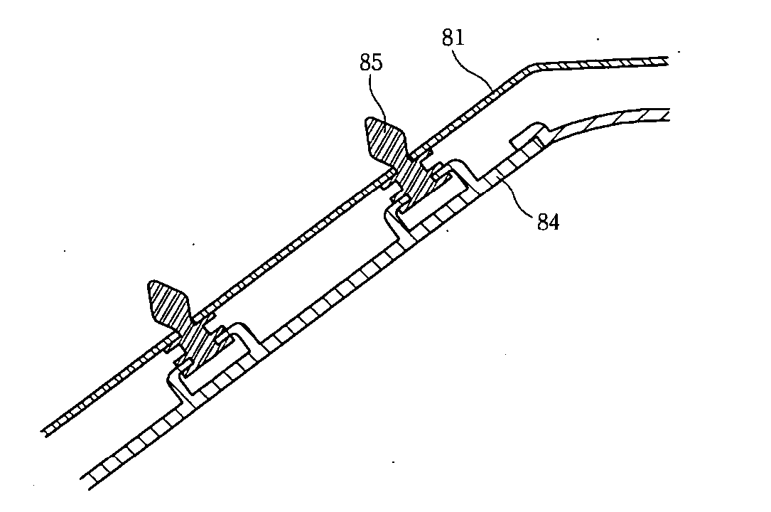
[0008] The present invention provides an A-pillar mounting structure for a curtain airbag in which a trim is separated from a vehicle body without forming a sharp part during deployment of an airbag. The separated A-pillar trim is prevented from being separated from the A-pillar by more than a predetermined distance so that it is prevented that the A-pillar collides with a passenger so as to hurt the passenger, thereby preventing the cap from being scattered.
[0009] An exemplary embodiment of the present invention provides an A-pillar mounting structure in which a curtain airbag is installed and to which an A-pillar trim is coupled. The A-pillar trim includes an A-pillar trim boss for connecting the A-pillar trim to an A-pillar, and an upper mounting member provided to an upper end of the A-pillar trim boss which is formed to be separable from the A-pillar trim boss during deployment of the curtain airbag. A coupling means is fixed to the A-pillar through the upper mounting member so that the A-pillar trim is coupled to the A-pillar. This structure enables the A-pillar trim to be easily separated from the A-pillar while preventing the A-pillar trim from being broken into sharp bits.
[0010] The A-pillar mounting structure may further include a cap. A receiving portion for receiving the cap may be formed at a lower end of the A-pillar trim boss of the A-pillar trim, and the cap may be connected to the coupling means or the mounting member through a cap scattering preventing means. Accordingly, the cap is prevented from being scattered, and the A-pillar trim can be prevented from being gone away from the A-pillar by the cap.

Problems solved by technology

At this time, the trim is separated to go away by deployment of the airbag, and the separated trim may collide with a passenger so that the passenger may be hurt.
In a structure as shown in FIG. 5, it is difficult for the curtain airbag 9 to be deployed, and the A-pillar trim 84′ is broken during deployment of the airbag so that the curtain airbag may be damaged or a passenger may be hurt by being hit by the broken trim.

Method used


Image

  • Pillar structure of curtain airbag
  • Pillar structure of curtain airbag
  • Pillar structure of curtain airbag

Examples


Embodiment Construction

[0027] An exemplary embodiment of the present invention will hereinafter be described in detail with reference to the accompanying drawings.

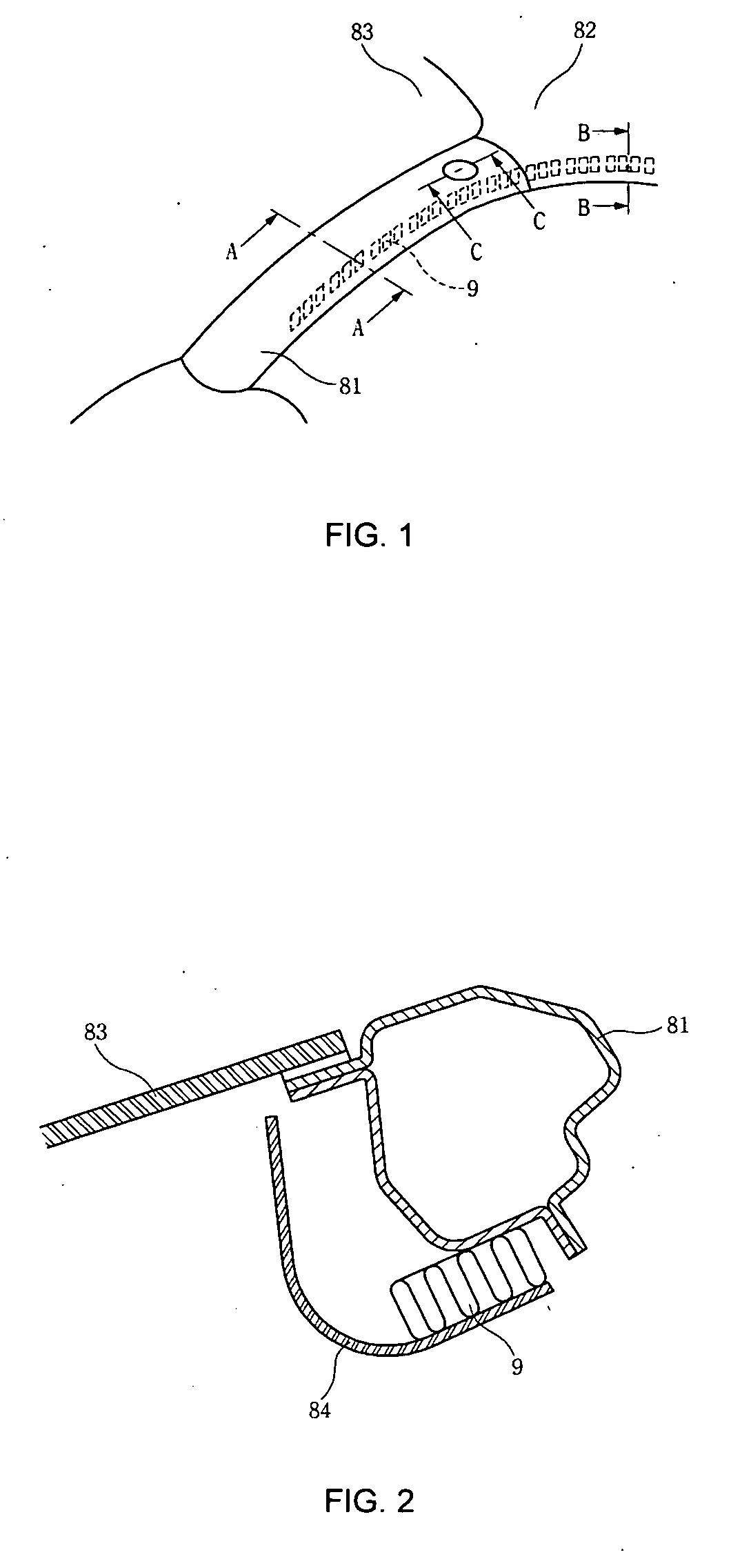
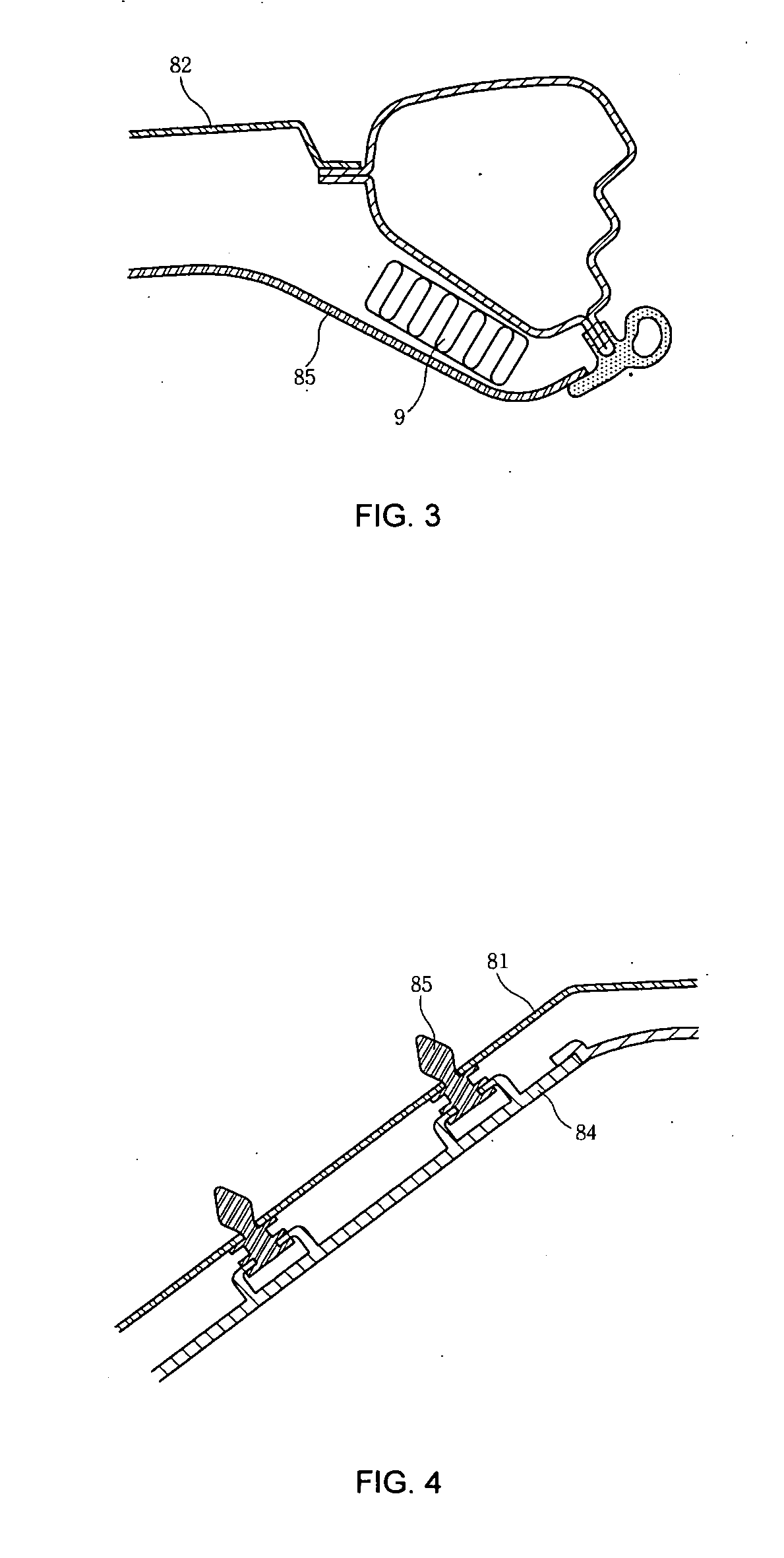
[0028]FIG. 1 is a perspective view of an A-pillar in which a curtain airbag is installed. FIG. 2 is-a cross-sectional view taken along a line A-A of FIG. 1. FIG. 3 is a cross-sectional view taken along a line B-B of FIG. 1. Referring to FIG. 1, a curtain airbag 9 is disposed above a side glass of a vehicle along an A-pillar 81, and it is deployed in response to a broadside collision so as to spread out along a side surface within a vehicle. Referring to FIG. 2, the airbag 9 is installed within an A-pillar trim 84 in a portion of the A-pillar 81 of a portion of a frame of a windshield glass 83. Referring to FIG. 3, the airbag 9 is installed within an indoor roof member 85 in a portion of a frame in a portion of a roof 82. In particular, as shown in FIG. 2, when the airbag is deployed from a portion of the A-pillar 81 of a portion of a frame of t...


PUM


Abstract

The present invention relates to an A-pillar mounting structure of a curtain airbag. In particular, an A-pillar mounting structure in which an upper mounting member of a boss of an A-pillar trim is separated from the during deployment of an airbag and the trim separated from the A-pillar is prevented from going far away by a cap that is prevented from being scattered by a cap scattering preventing means connected to a mounting member or a trim connecting means. The present invention relates to an A-pillar mounting structure. in which a curtain airbag is installed and to which an A-pillar trim is coupled. The A-pillar trim includes an A-pillar trim boss for connecting the A-pillar trim to an A-pillar, and an upper mounting member provided to an upper end of the A-pillar trim boss and formed to be separable from the A-pillar trim boss during deployment of the curtain airbag.

Description

CROSS-REFERENCE TO RELATED APPLICATION [0001] This application claims priority to Korean Patent Application No. 10-2005-0116552 filed in the Korean Intellectual Property Office on Dec. 1, 2005, the disclosures of which are incorporated herein by reference. BACKGROUND OF THE INVENTION [0002] (a) Field of the Invention [0003] The present invention relates to an A-pillar mounting structure for a curtain airbag in which an upper mounting member of a boss of an A-pillar trim is separated from the boss during deployment of an airbag. A cap is prevented from being scattered by means connected to a mounting member or a trim connecting means which prevents the separated A-pillar trim from being separated from the A-pillar so that a passenger is prevented from being hurt by the separated A-pillar or the scattered cap. [0004] (b) Description of the Related Art [0005]FIG. 1 is a perspective view of an A-pillar in which a curtain airbag is installed. FIG. 2 is a cross-sectional view taken along ...

Claims


Application Information

Patent Timeline
IPC IPC(8): B60R13/01B60R21/21
CPCB60R13/0206B60R13/025B60R21/213B60R2013/0287B62D25/04
Inventor CHOI, HYEONG HO
Owner HYUNDAI MOTOR CO LTD
Learn More