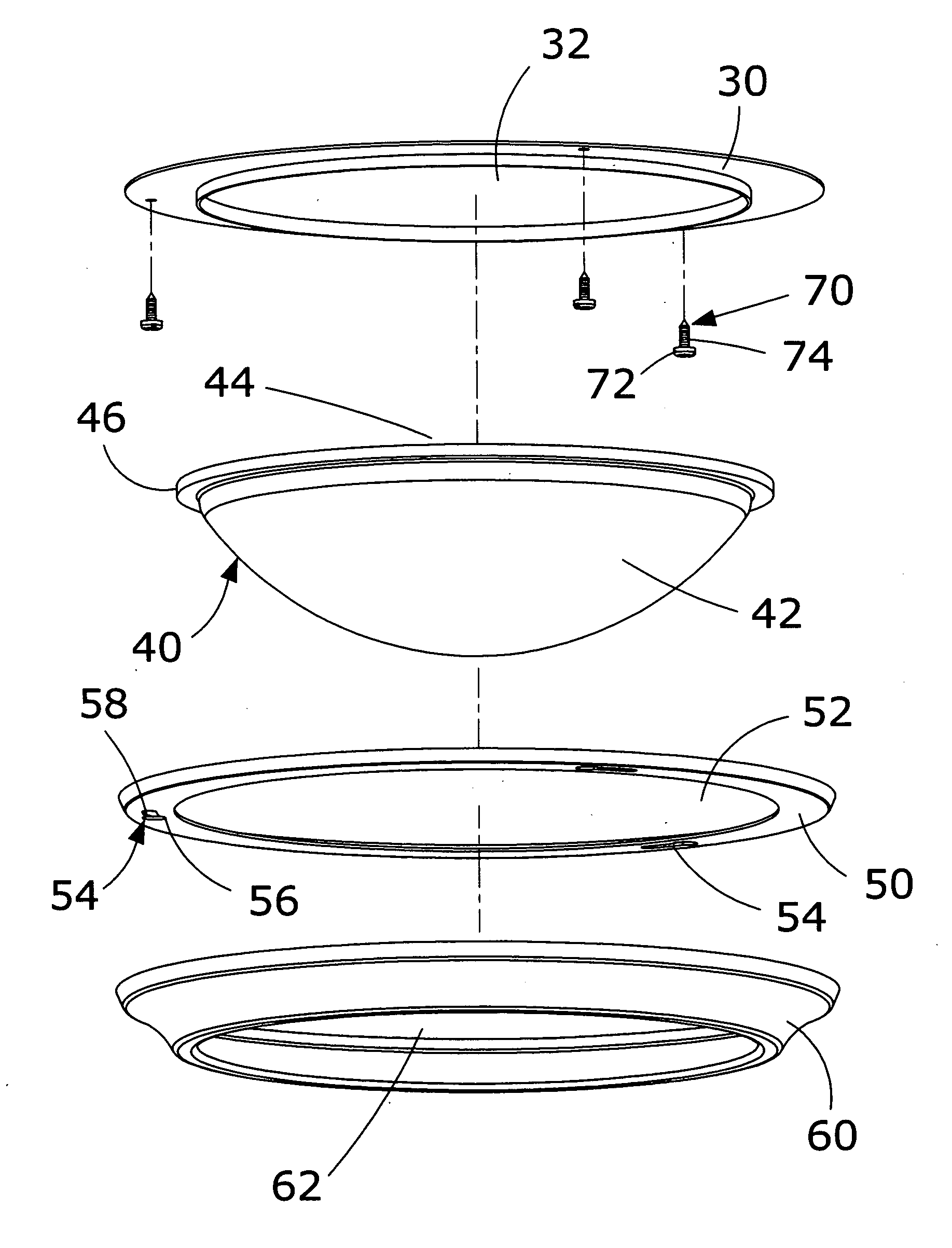
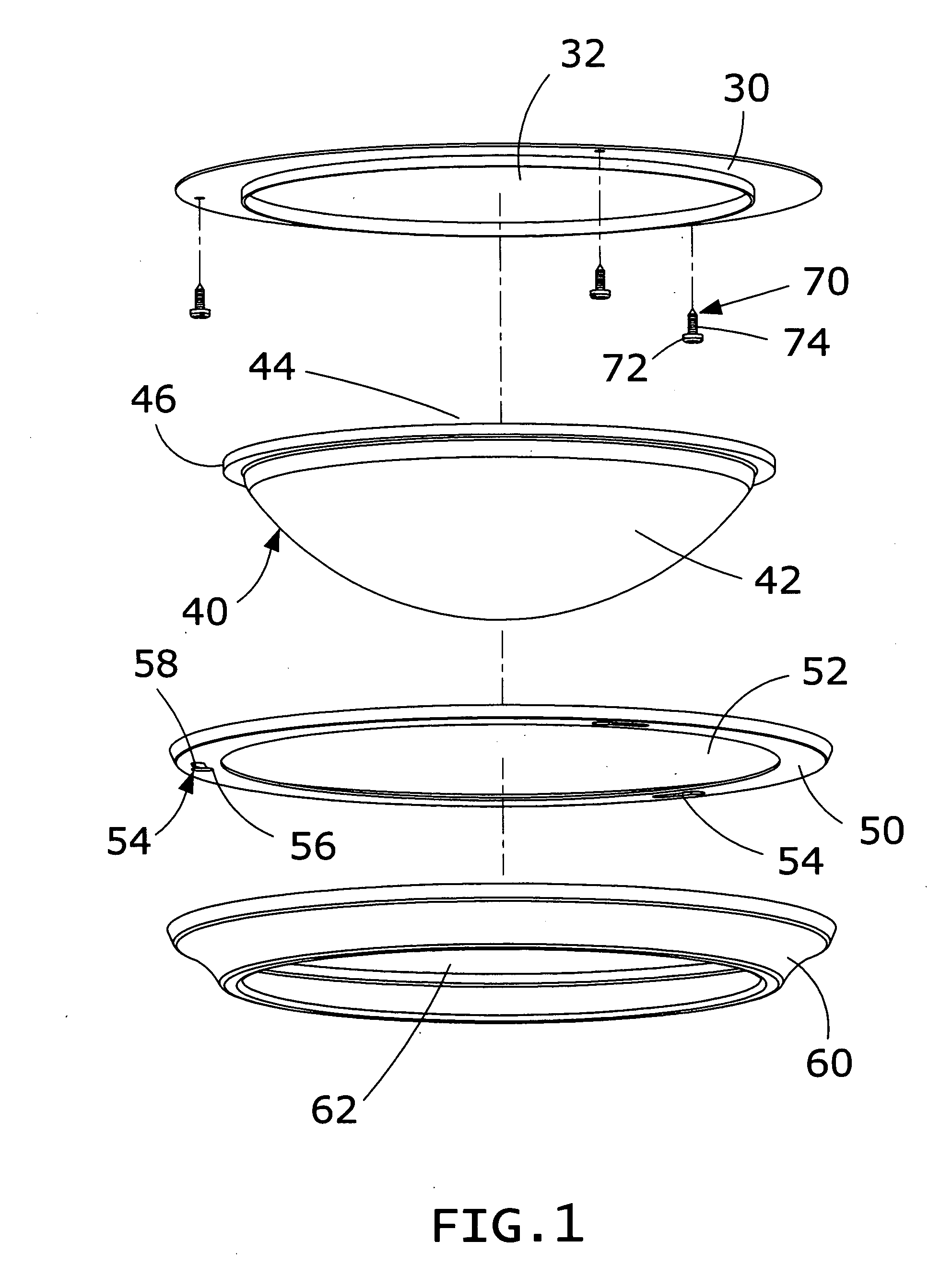
[0027] Referring to the drawings and initially to FIGS. 1-5, a wall lamp in accordance with the preferred embodiment of the present invention comprises a positioning disk 30, a lamp shade 40, a connecting disk 50, and a retaining disk 60.
[0028] The positioning disk 30 has an annular shape and has a central portion formed with a through hole 32.
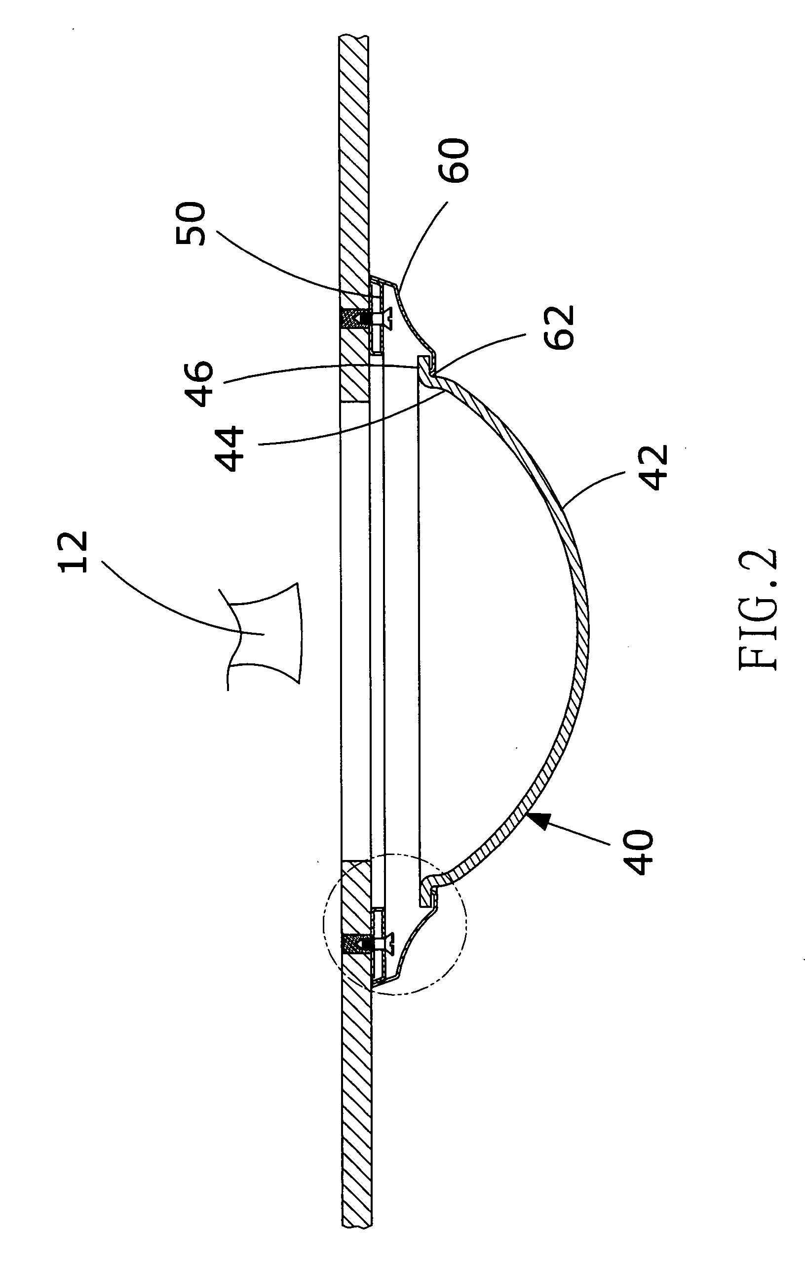
[0029] The lamp shade 40 has a first end formed with an arc-shaped face 42 and a second end formed with an opening structure 44 having a periphery formed with a radially and outwardly extending annular lip 46.
[0030] The retaining disk 60 has an annular shape and has a central portion formed with an opening 62.
[0031] The connecting disk 50 has an annular shape and has a central portion formed with an opening 52. The connecting disk 50 has an annular face formed with a plurality of connecting slots 54 each consisting of two holes having different diameters. Each of the connecting slots 54 of the connecting disk 50 has a first end formed with a receiving portion 56 and a second end formed with a locking portion58 having a dimension (or diameter) smaller than that of the receiving portion 56. In the preferred embodiment of the present invention, the locking portion 58 of each of the connecting slots 54 of the connecting disk 50 is an elongated hole so that the dimension of the locking portion 58 of each of the connecting slots 54 of the connecting disk 50 means a width in the transverse direction of the elongated hole.
[0032] Referring to FIGS. 1-3, the positioning disk 30 is secured to a ceiling 19 by a plurality of fastening members 70. Thus, the wall lamp is mounted on the ceiling 19, and the electric bulb 12 of the wall lamp is inserted into the ceiling 19. Each of the fastening members 70 is preferably a locking screw. Each of the fastening members 70 has a first end formed with a head portion 72 and a second end formed with a shank portion 74 having a diameter smaller than that of the head portion 72. The shank portion 74 of each of the fastening members 70 is partially extended through the positioning disk 30 and inserted into the ceiling 19 and partially protruded outward from the positioning disk 30, so that a gap 76 is defined between the head portion 72 of each of the fastening members 70 and the positioning disk 30.
[0033] The connecting disk 50 and the retaining disk 60 are integrally combined together by soldering. The lamp shade 40 is mounted in a combination of the connecting disk 50 and the retaining disk 60, and the arc-shaped face 42 of the lamp shade 40 is protruded outward from the opening 62 of the retaining disk 60.
[0034] Referring to FIGS. 1-5, the receiving portion 56 of each of the connecting slots 54 of the connecting disk 50 has a diameter greater than that of the head portion 72 of each of the fastening members 70, and the locking portion 58 of each of the connecting slots 54 of the connecting disk 50 has a diameter greater than that of the shank portion 74 of each of the fastening members 70 and smaller than that of the head portion 72 of each of the fastening members 70.
[0035] Referring to FIG. 4, when each of the connecting slots 54 of the connecting disk 50 is fitted onto the respective fastening member 70, the receiving portion 56 of each of the connecting slots 54 of the connecting disk 50 aligns with the head portion 72 of the respective fastening member 70, so that the head portion 72 of each of the fastening members 70 can be inserted into the receiving portion 56 of the respective connecting slot 54 of the connecting disk 50.
[0036] Referring to FIG. 5, the connecting disk 50 is rotatable relative to the positioning disk 30 and the fastening members 70, so that the shank portion 74 of each of the fastening members 70 can be inserted into the locking portion 58 of the respective connecting slot 54 of the connecting disk 50. At this time, the locking portion 58 of each of the connecting slots 54 of the connecting disk 50 has a diameter smaller than that of the head portion 72 of each of the fastening members 70, so that the connecting disk 50 is locked onto the positioning disk 30 by the fastening members 70.
[0037] Referring to FIG. 2, the annular lip 46 of the lamp shade 40 is rested on a periphery of the opening 62 of the retaining disk 60, so that the lamp shade 40 is retained by the retaining disk 60.
[0038] Referring to FIG. 6, the opening structure 44 of the lamp shade 40 has a diameter greater than that of the opening 62 of the retaining disk 60, so that the lamp shade 40 is directly retained by the opening 62 of the retaining disk 60.
[0039] Referring to FIGS. 7 and 8, the wall lamp is mounted on a light steel frame structure which includes two opposite steel frames 84 each suspended by a metallic wire 87, a plaster board 82 mounted between the two opposite steel frames 84 and formed with a plurality of through holes 88, and a plurality of fastening members 90 each mounted on the plaster board 82 and each extended through the respective through hole 88 of the plaster board 82 to connect the connecting disk 50 of the wall lamp. Each of the fastening members 90 is preferably a toggle bolt. Each of the fastening members 90 includes a threaded shank portion 96 extended through the respective through hole 88 of the plaster board 82, a head portion 94 formed on a first end of the shank portion 96 and protruded outward from a lower face of the plaster board 82, two opposite wings 92 each pivotally mounted on a second end of the shank portion 96 and each rested on an upper face of the plaster board 82, and a locking nut 100 screwed onto the first end of the shank portion 96 and rested on the positioning disk 30 to lock the positioning disk 30 onto the lower face of the plaster board 82. A gap 97 is defined between the head portion 94 and the locking nut 100 of each of the fastening members 90. The head portion 94 of each of the fastening members 90 has a diameter greater than that of the shank portion 96.
[0040] Referring to FIGS. 7 and 8 with reference to FIG. 1, the receiving portion 56 of each of the connecting slots 54 of the connecting disk 50 has a diameter greater than that of the head portion 94 of the fastening members 90, and the locking portion 58 of each of the connecting slots 54 of the connecting disk 50 has a diameter greater than that of the shank portion 96 of each of the fastening members 90 and smaller than that of the head portion 94 of each of the fastening members 90.
[0041] In assembly, when each of the connecting slots 54 of the connecting disk 50 is fitted onto the respective fastening member 90, the receiving portion 56 of each of the connecting slots 54 of the connecting disk 50 aligns with the head portion 94 of the respective fastening members 90, so that the head portion 94 of each of the fastening members 90 can be inserted into the receiving portion 56 of the respective connecting slot 54 of the connecting disk 50.
[0042] In operation, the connecting disk 50 is rotatable relative to the positioning disk 30 and the fastening members 90, so that the shank portion 96 of each of the fastening members 90 can be inserted into the locking portion 58 of the respective connecting slot 54 of the connecting disk 50. At this time, the locking portion 58 of each of the connecting slots 54 of the connecting disk 50 has a diameter smaller than that of head portion 94 of each of the fastening members 90, so that the connecting disk 50 is locked onto the positioning disk 30 by the fastening members 90.
[0043] Accordingly, the connecting disk is locked onto and detached from the positioning disk by rotating the connecting disk relative to the fastening members, so that the wall lamp is assembled and dismantled easily and rapidly, thereby facilitating a user assembling and disassembling the wall lamp, and thereby saving the working time. In addition, the fastening members are wholly hidden in the retaining disk, thereby enhancing the aesthetic quality of the wall lamp.
[0044] Although the invention has been explained in relation to its preferred embodiment(s) as mentioned above, it is to be understood that many other possible modifications and variations can be made without departing from the scope of the present invention. It is, therefore, contemplated that the appended claim or claims will cover such modifications and variations that fall within the true scope of the invention.